13. Calibration - Touch Sense
Tutorial
This tutorial covers the options available when using the touch sense calibration type.
Prerequisites and Resources
This tutorial will cover a deeper look at the touch sense calibration type we looked at briefly in the Calibration Setting’s Overview tutorial. If you haven’t completed that tutorial, it’s recommended that you visit that first to get a general understanding of all the various options in the calibration settings.
Before starting with the tutorial, ensure to have the KUKA KR8 example cell downloaded and imported into Verbotics Weld. This cell is available to download here.
This walkthrough also uses the touch sense example project which can be downloaded here.
Video Tutorial
Step by Step Guide
Step 1 - Specifying The Number of Sensing Motions
Once you’ve loaded into the example project, we can get started by navigating to the weld settings, then focussing on the several calibration settings we’ve created using the touch sense calibration mode. Using touch sense allows us to specify several specific options in addition to the general options covered in our overview tutorial. Select the default “touch sense” setting, you’ll now see the 5 touch-sense unique options proceeding the general options.
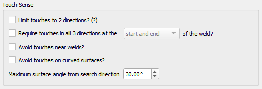
Touch Sense Options
Start with the first 2 of these options, being the Limit touches to 2 directions and the Require touches in all 3 directions option. Using these options, we can either limit the robot to only sense in directions perpendicular to the weld path or force the robot to conduct 3 sensing motions per weld.
Return to the viewer, where we’ll to see these 2 options in effect. In the welds widget you’ll find 6 example welds. For these 2 options, we’ve created 2 calibration settings and applied them to the 2 long example welds:
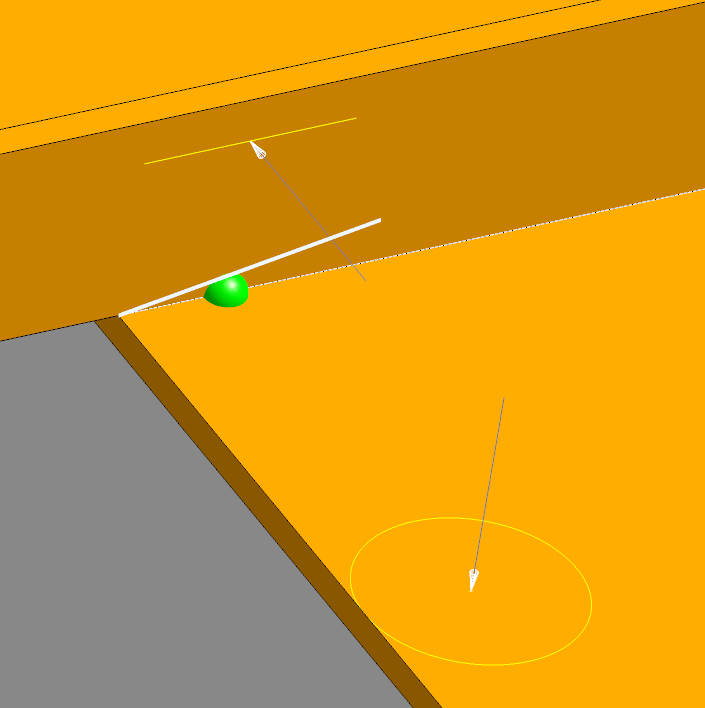
Select and view “Long Example Weld 1”. Upon selecting this weld, you’ll see circles appear on the part representing the touch sense locations. Notice how with the limit touches option enabled, there are 2 sensing actions per point along the weld.
Select and view “Long Example Weld 2”. For this weld, it alternatively requires a 3rd touch sense located at least at one of the 2 ends of the weld.
We can even see these both in action by using the weld simulator, which we can do by selecting one of the 2 long example welds in the program widget and clicking play in the viewer.
Limit to 2 Touches |
Require 3 Touches |
|---|---|
|
|


Step 2 - Avoiding Features During Sensing
Return back to the welds widget. These next 2 options allow us to specify certain areas for the robot to avoid during sensing. These being Avoid touches near welds and Avoid touches on curved surfaces. Avoiding these areas can reduce inaccurate calibration readings.
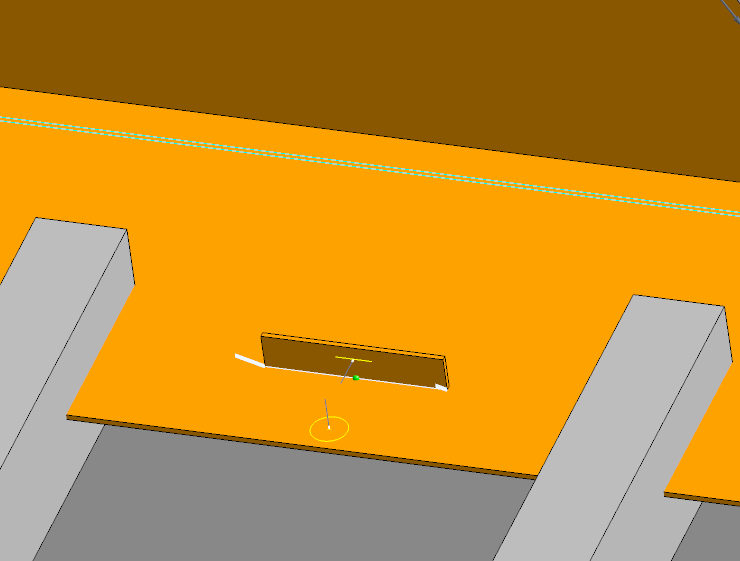
Select “Very Short Example Weld 1”, take note of where the touch sense is performed when not avoiding these features. However, now shift to “Very Short Example Weld 2”. You’ll notice not only does the sense on the baseplate retreat slightly, but the sense to be conducted on the vertical plate has shifted to the rear wall of the firepit to avoid the weld.
Default Sensing |
Avoiding Features |
|---|---|
|
|
Step 3 - Limiting Search Angle
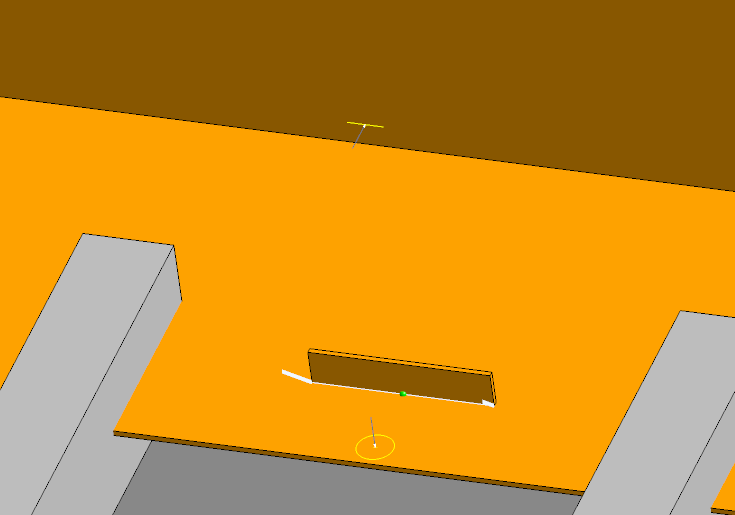
The final touch sense specific option is the Maximum Surface angle from search direction. This options allows for limiting the change in direction from the search angle when completing a sensing motion. For this last option, focus on the short examples welds.
We halved the maximum surface angle for “Short Example Weld 2” to 15°, which you’ll notice completes the touch sense at an angle much closer to the search direction when compared to the first weld with this angle instead restricted to a value of 30°:
30° |
15° |
|---|---|
|
|