2. User Interface
Tutorial
This tutorial shows how to use the User Interface and explores its various functions, navigations and shortcuts.
Prerequisites and Resources
Before starting with the tutorial, ensure to have the Universal Robots UR10e example cell downloaded and imported into Verbotics Weld. This cell is available to download from the examples page on our website.
Further, this walkthrough uses the UI example project which can be downloaded here.
User Interface Key
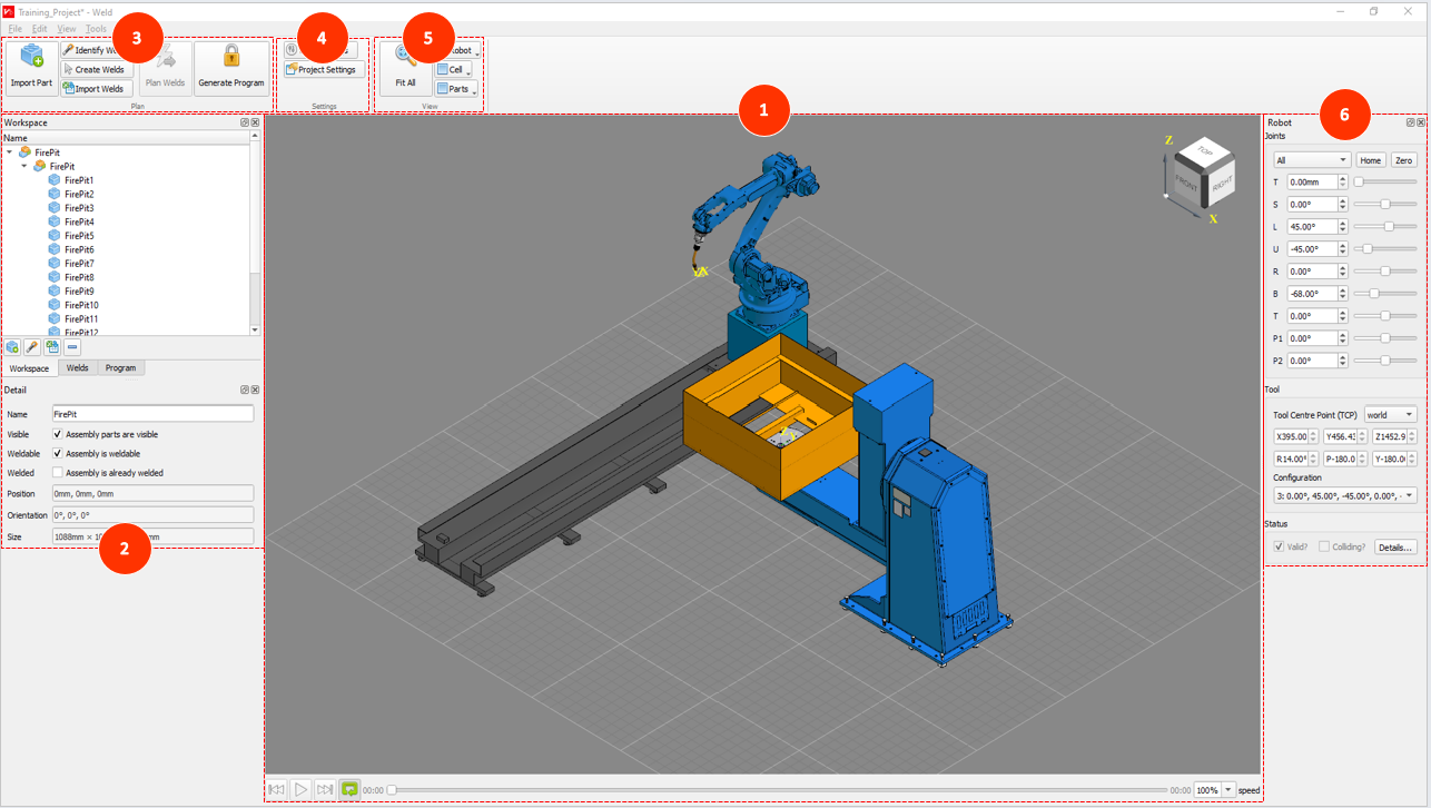
1. 3D Viewing Window
2. Workspace
3. Plan Ribbon Tab
4. Settings Ribbon Tab
5. View Ribbon Tab
6. Robot Positioning
Step by Step Guide
Exploring the Verbotics Weld User Interface
Customising the UI
The UI consists of several widgets, ribbons and a large viewer window, of which is entirely customisable to best suit your needs. Clicking and dragging a widget will allow you to pop it out of the dock and move it around as a window, allowing it to be placed anywhere on the screen or even on a second monitor. Dragging a widget over the left or right docks will allow you to overlay widgets with one another.
If you lose a certain widget, or prefer the default layout, you can always revert the layout by selecting reset layout in the view tab of the top menu.
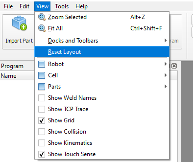
Reset Layout
Navigating the 3D Viewing Window
The largest section of the user interface is the 3D Viewing Window, also known as the Viewer. This window will display the cell and any assemblies you import into the project. As you can see, we’ve got the Universal Robots cell visible with the small example part on the table surface. We can adjust this view in different ways using the mouse buttons in combination with the View Cube seen in the top right corner of the Viewer. These include:
Clicking and holding the right mouse button allows us to pan across the viewer.
Clicking and holding the left mouse button allows us to rotate around the current selection in the viewer. If nothing is selection, this will instead be the centre of the assembly.
Select individual parts by left clicking them with the mouse.
Select multiple parts by shift clicking and dragging the mouse over the desired parts or by holding control and clicking all the parts you want to select one by one.
Scrolling with the mouse wheel allows you to zoom in or out of the pointer’s location.
To view a specific face or corner, we can click on the View Cube.
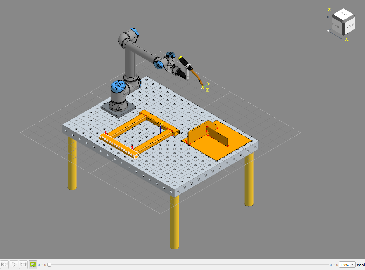
Viewer
In addition to view adjustment, using the player buttons at the bottom of the viewer we can also simulate any welds that have valid plans.
Widgets
Moving on, let’s look at the dock left of the Viewer. The upper section is a shared space which we can select to display the workspace which shows all imported assemblies and parts, welds which displays all created welds, and program which shows all planned welds and their associated program to be sent to the robot.
Looking at the program widget, you’ll notice this tab currently contains a list of commands each telling the robot what action to undertake. We can further also see a simulation of this in the viewer. Let’s look at the bottom of the viewer, where you’ll see the simulation controls. Go ahead and select the Go Home step in the program widget, then click play. The viewer will start to play out the simulation. We can select previous to return to the previous step, or select next to advance to the next step. We can also slow or speed up the simulation using the speed drop down box on the far right.
Below the program widget, you’ll find the details widget which displays the detailed information about the currently selected item. If we go ahead and click on the cylinder on the sample part, we can see its details are now displayed.
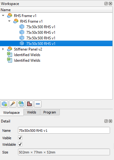
Left Side Widgets
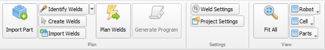
Ribbon Menu
At the top of the screen is the ribbon, which is made up of 3 tabs.
The Plan tab, where you’ll find most options regarding the creation of parts, welds and the overall program.
The Settings tab which links to settings for welds or settings for the overall project.
The View tab, which has options allowing us to adjust the appearance of the robot, cell and parts, as well as the Fit-all function, which lets us adjust the view to observe the entire assembly and robot.
Ribbon Menu
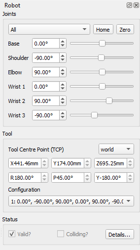
Robot Controls
The final section of the UI to explore is the dock to the right of the viewer, labelled Robot. In this dock, we can use the joints section to adjust the rotation of the robots limbs to change the positioning of the robot which we can revert by clicking the home button to return the robot to its original position. In addition, we can also click the zero button, to set all limb rotations to zero.
The tool section lets us determine the location of the tool’s centre point relative to either the workpiece or the overall world. Finally, the status section tells us if the current position of the robot is valid or if there are collisions.
Robot Controls