5. Fixtures and Assemblies
Tutorial
This tutorial will walk you through the full extent of the various components you can import into Verbotics Weld. It’ll explore importing supports, fastening devices and multi-part assemblies as well as how to prepare these for proper use in your welding project.
Prerequisites and Resources
Before starting with the tutorial, ensure to have downloaded and installed the ABB FlexArc Example cell which is available from our website.
In addition, make sure to have downloaded the weld table and workpiece assembly example parts.
Video Tutorial
Step by Step Guide
Step 1 - Fixtures and Supports
The first part of this tutorial looks at importing and preparing fixtures/supports. In addition to the regular parts you would import to be welded, tables that would support your workpiece and fixtures that hold parts in place can also be imported.
Importing and Preparing a Workpiece Table
The initial plate for the ABB Flexarc Sample Cell isn’t able to hold or support our part properly. To fix this, we’ll import a step file of a weld table to be attached to the workpiece positioner.
Open the
import partfunction and select the “weld_table.step” fileOnce the table has loaded in, select the “weld_table” from the workspace widget and open the
transform/rotatefunction from the context menu (right-click on part in workspace to see context menu).Using the values shown in the table below, adjust the “weld_table’s” position, then click
OKto confirm the transform.
Option |
Value |
Translate X |
383.0 mm |
Translate Y |
449.0 mm |
Translate Z |
-360.0 mm |
Rotate R |
90° |
Rotate P |
0° |
Rotate Y |
0° |
With the table imported, the final step for preparing the table is to set the component to act as a support instead of a weldable part. This can be done in 2 ways:
Right-click on the “weld_table” in the workspace widget and uncheck the
weldableoption.Select the “weld_table” in the workspace widget, then in the details widget below uncheck the box labelled
weldable.
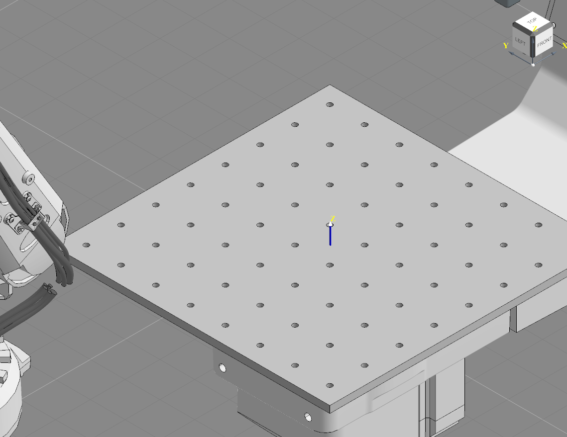
Table Prepared as a Support
Importing the Workpiece and Preparing the Fasteners
With the table in-place, the next step is to import the workpiece:
Open the
import partfunction and select the “workpiece_assembly.step” fileSelect the “workpiece_assembly” from the workspace widget and open the
transform/rotatefunction from the context menu (right-click on part in workspace to see context menu).Using the values shown in the table below, adjust the position of the “weld_table”, then click
OKto confirm the transform.
Option |
Value |
Translate X |
0 |
Translate Y |
0 |
Translate Z |
40.0 mm |
Rotate R |
90° |
Rotate P |
45° |
Rotate Y |
0° |
You should now have a workpiece sitting upright on the table. Now we can go ahead and prepare the fasteners. To do so, navigate to the group of parts named “clamps” in the workspace.
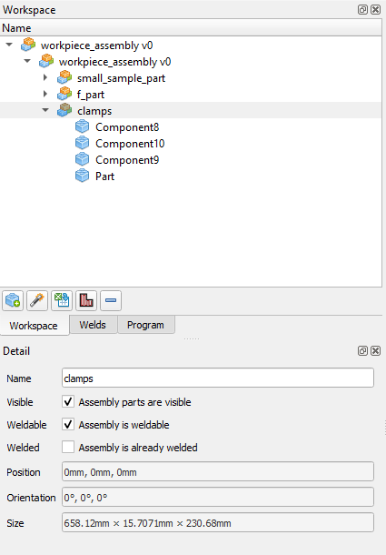
Clamps Sub-Assembly
These 4 clamps will be used to hold our workpiece in place, however once again we need these to be considered as supports and to not be weldable. Similar to before, select the “clamps” from the workspace and then uncheck the weldable option.
Non-Weldable Clamps
Note
When parts are checked as weldable, they will appear as yellow whereas parts that aren’t weldable will appear as grey. Sub-assemblies set as “already welded” will appear as orange.
Step 2 - Assemblies and Preparing Sub-Assemblies
Upon importing the workpiece, you may have noticed the assembly consisted of several sub-groups of parts. These sub-groups are referred to as sub-assemblies, and with verbotics, we can adjust and manipulate sub-assemblies independently from the rest of the assembly without needing to detach the two.
Starting at the top-most layer, you can see our “weld_table” and our “workpiece_assembly”. If we were to select the “table_assembly”, you’d see every part that makes up that table. Any adjustments we make at the assembly level will affect every part and sub-assembly it consists of.
Moving on, if we click the arrow next to the workpiece assembly, you’ll see how now it’s expanded to show its 3 sub-assemblies. At this level, we can select sub-assemblies and apply specific adjustments to each one. We already did this before with the clamps sub-assembly when we set them as not-weldable, however we also can move, rotate and alter the visibility of sub-assemblies.
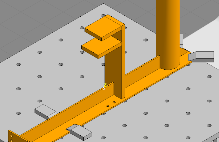
Let’s try this out with the sub-assembly labelled “f_part”.
Select “f_part” from the workspace, then right-click and open
transform/rotate.Instead of using the transform window to adjust the position, click and drag the part in the view to move it relative to the workpiece assembly.
Move the “f_part” slightly along the workpiece then click
OK.
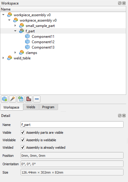
In addition to the weldable option we explored previously, assemblies and sub-assemblies can also be set as already welded. Select the “f-part” in the workspace and locate this option in the details widget.
Altering the f_part Sub-Assembly
For this project, the “f_part” has already had its 3 parts welded previously, so check the welded checkbox.
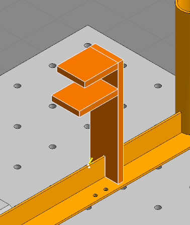
f_part Sub-Assembly Prepared as Already Welded
Finally, let’s click the arrow left of the small assembly part in the workspace. This will expand to now show all the parts making up the sub-assembly. Here, we can adjust each part individually, however many of the options regarding parts has been covered in our previous tutorials.