2D Calibration Editor
The calibration editor allows you to semi-automatically create or edit 2D calibration for your weld path. By default Verbotics Weld will automatically plan calibration for your weld path, but you can use the 2D calibration editor to create or adjust a calibration plan as well.
Before using the editor, you need to tell Verbotics Weld about the joint types you have set up in your sensor and their behaviour. See the Weld Settings reference for information on how to do this.
To access the 2D calibration editor, right click on a weld and select either “Create 2D Laser”, or “Edit 2D Laser” to edit an existing calibration. This will open the dialog shown below. When you click “Create 2D Laser”, Verbotics will automatically populate the dialog with suggested locations along to the weld to sense.
Note
The weld must have a toolpath available before you can create or edit calibration.
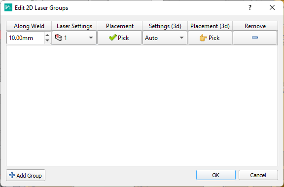
The calibration editor dialog.
Each row in the dialog corresponds to a location along the weld path that will be calibrated using the sensor. To add a new location (also called a group), click the “Add” button in the bottom left of the dialog. To remove a location, click the remove button in the corresponding row.
The laser sense locations are shown in the main 3D viewer with a green sphere, and a preview of the laser sensor profile and tool.
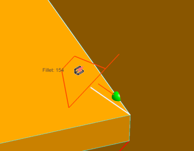
Sense location.
Modifying a Sense Group
To modify a sense group, use the buttons in the table row. The available options are:
Along weld modifies the sense location along the weld length.
Laser settings lists the available settings that you have defined for use, along with an icon indicating their type. You can choose “Auto” in this menu to have Verbotics choose the best joint type for the location you are picking.
Pick when clicked will allow to to click in the main 3D viewer to choose the position along the weld path to sense with the laser. This will used the selected joint type (or attempt to determine the best joint type if you have selected “Auto”) and will show a preview of the laser sensor inside the viewport. This will be coloured green when a valid location is detected. The icon on the Pick button will be a finger if a location is required, or a tick if it is valid.

Interactive picking of a fillet laser sense location.

Interactive picking of a edge sense location.
Settings (3d) and Placement (3d) allow you to choose an optional third direction perpendicular to calibrate with. This will calibrate the offset parallel to the weld path. Automatic planning for third direction is currently not supported, so this will need to be manually selected if required.
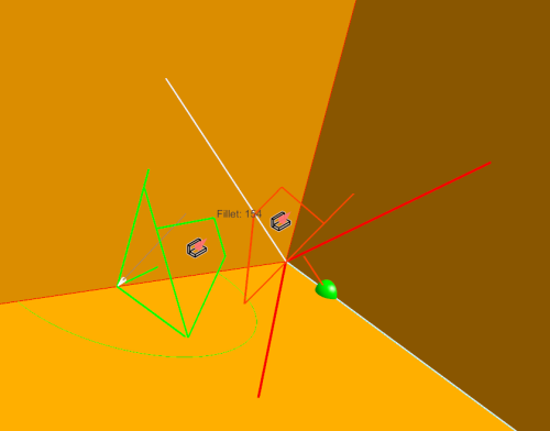
Selection of a third-direction (3d) sense location perpendicular to the main search. This will calibrate the start position along the weld path direction.
Applying Changes
Once you are happy with the sense data, click the “OK” button in the dialog. The planning process will need to be run to finalise planning the rest of the weld (e.g. motions between sense locations). Until this is done, the weld will be set to a “requires re-planning” status and cannot be exported.