Path Calibration
Path calibration is the process of sensing the workpiece and modifying the welding path so it more closely represents the intended position. There are several reasons why path calibration is required for a program that is created offline:
The robot manipulator and other equipment is not placed exactly as per the offline model.
The robot kinematics are not perfectly accurate.
Differences between the robot tooling and the offline model.
Differences between the workpiece and the offline model.
When programming online, these points above are not an issue. As the programmer is using the real world equipment and parts to determine the robot position, each of these errors is accounted for.
|
|
|
|
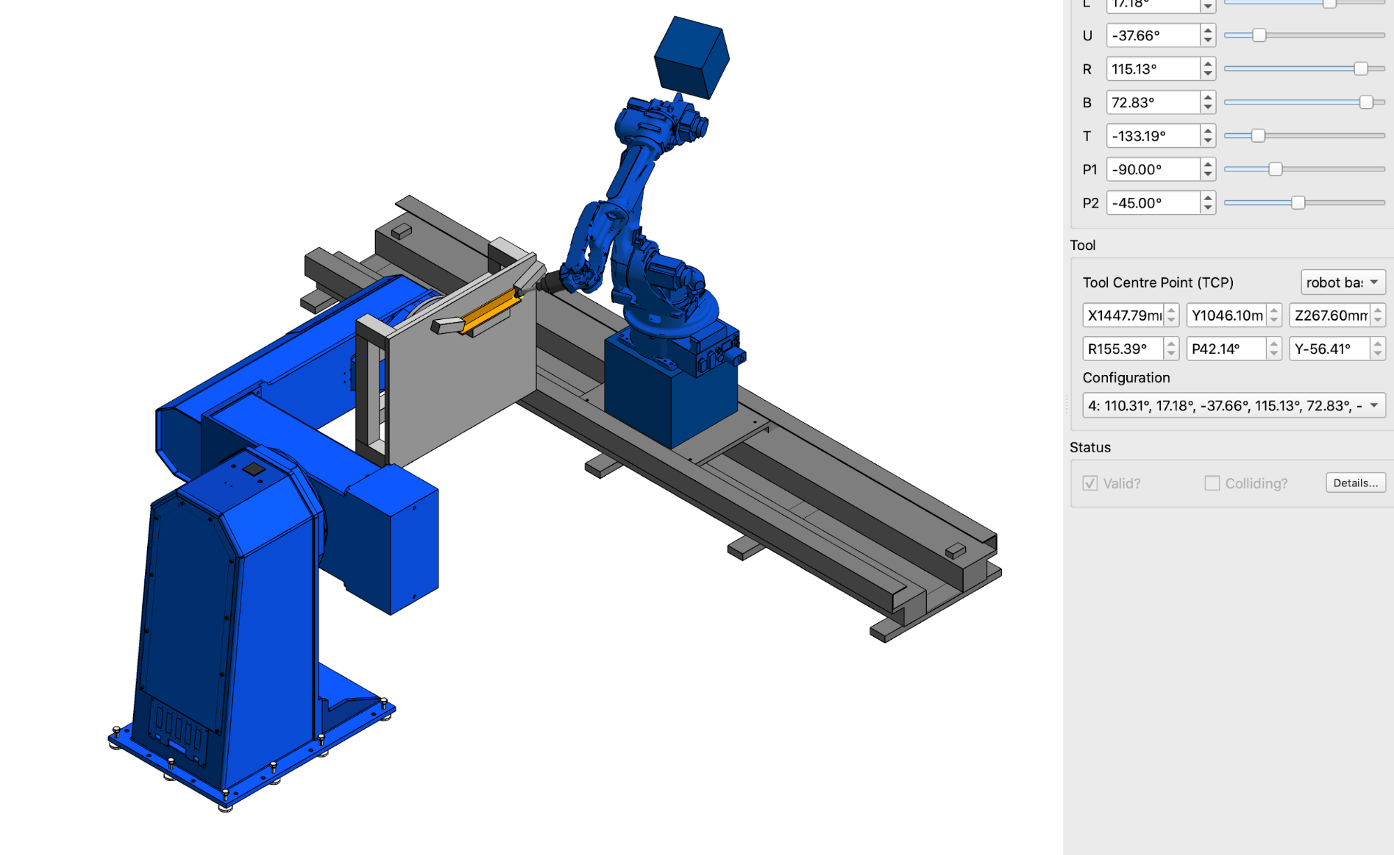
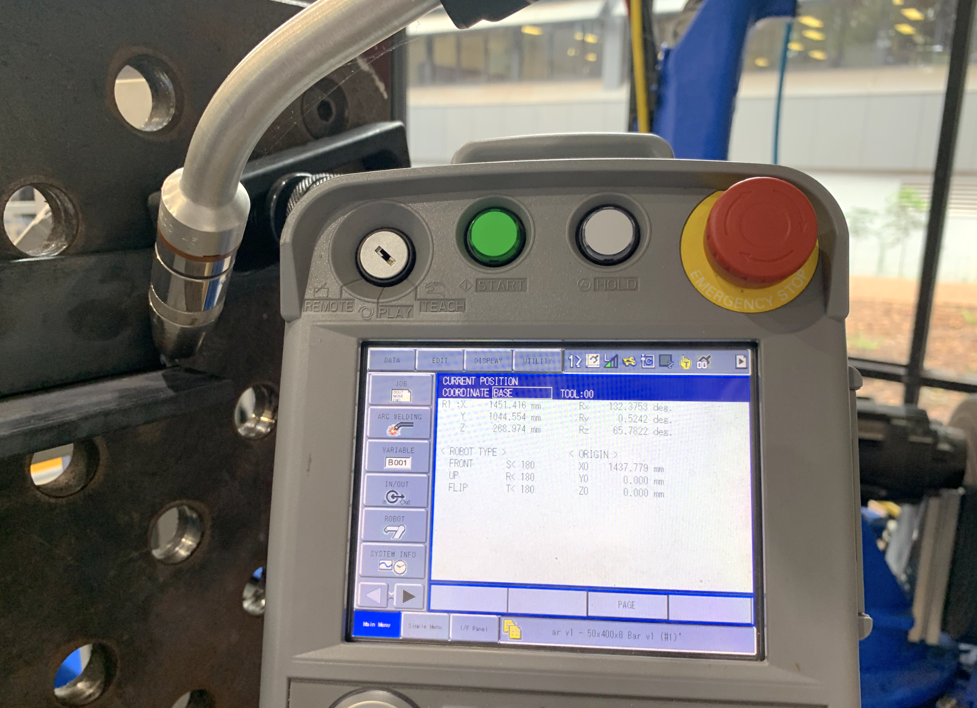
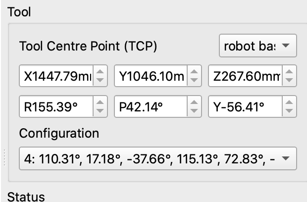
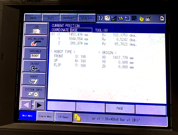
Left, the position of the robot at the start of the weld path in Verbotics Weld. This is the theoretical robot position as calculated based on a kinematically perfect robot with the calibration data provided by the customer. Right, the actual position of the real robot system when the wire is jogged to the start point of the weld. The error is X: 3.6mm Y: -1.5mm Z: 1.4mm. |
|
There are several options available to ‘re-align’ these offline paths to back to the real world workpiece. Each has its advantages and disadvantages depending on what the intended outcome is. Is the part something made in high volume where every second of tact time is critical? Is the workpiece something that can be calibrated using sensing? Are there slight changes part to part that need to be compensated for?
One option is to simply not plan welds without calibration and adjust the toolpath online with the teach pendant. In this method the program generated with Verbotics Weld will get the robot ‘close’ to the path and the user can modify the path point by point to the exact real world location.
The other option is to get the robot to sense the path offset and compensate for it. This is a little more complicated, and will not work for all paths, however this method requires the least amount of human effort. It will also allow the robot to adjust for slight differences between parts if this occurs. The cost for this is cycle time. Each sensing action takes some time and this may be an issue depending on your production circumstances.
The method this document will look at is using sensing on the robot to measure the difference between the real path in space and the theoretical path as defined from the CAD model.
Initially we will give a quick example of a path calibration and introduce some terminology that we use within Verbotics to describe this process. We will then discuss how this works within Verbotics Weld so you can gain a better understanding of what is going on when planning path calibration actions.
Fillet Weld Example
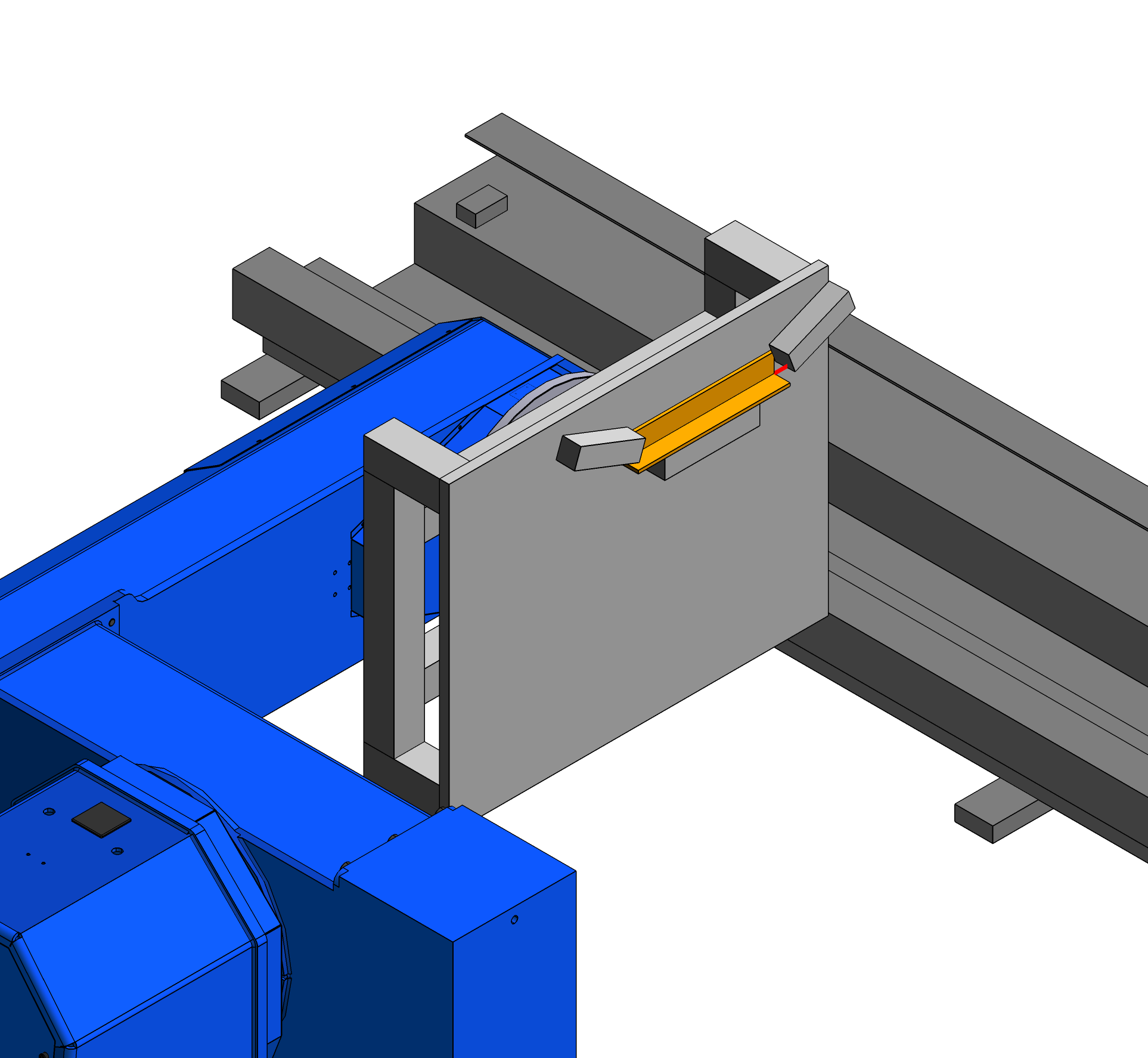
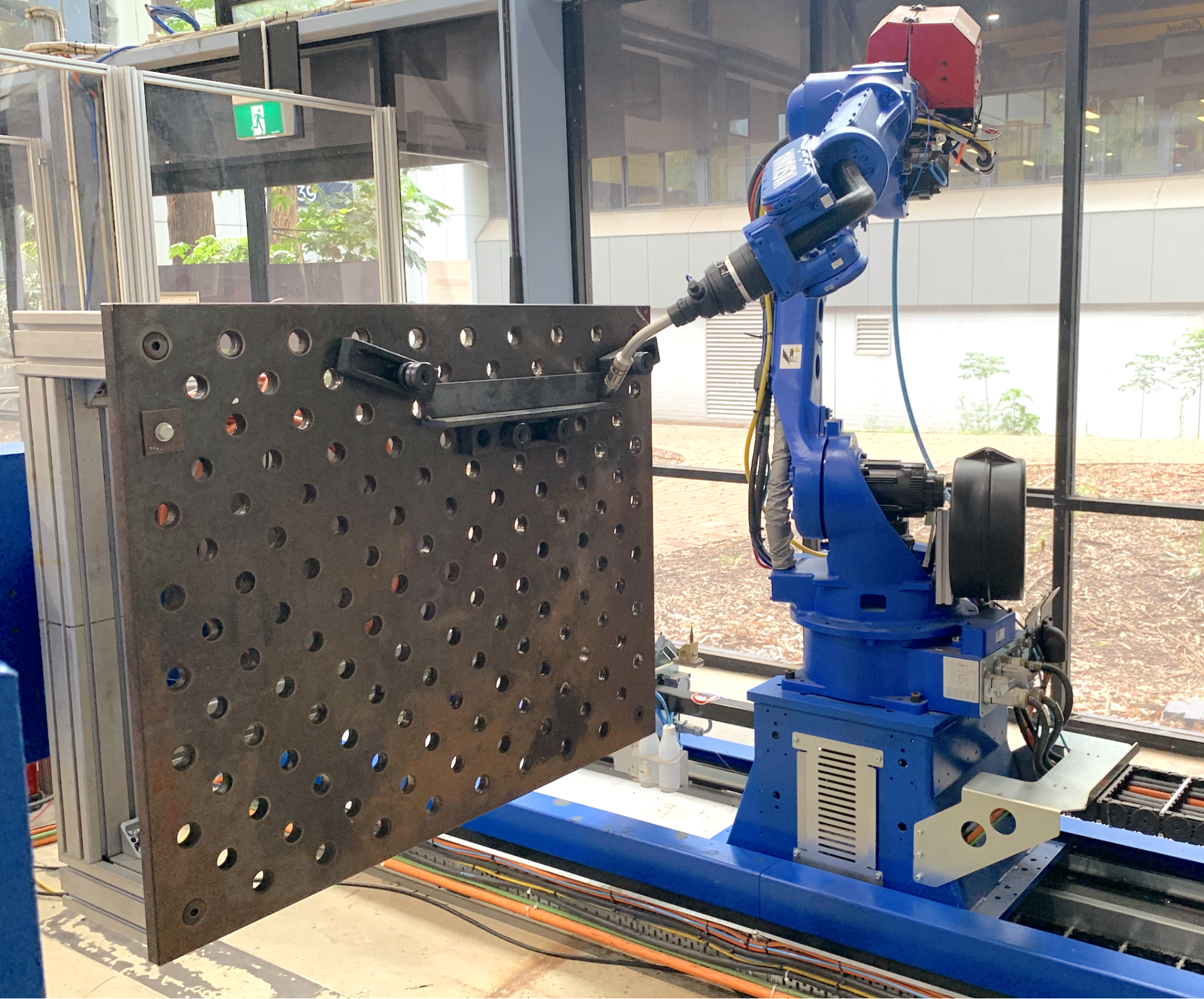
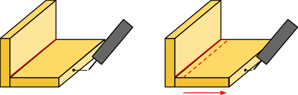
Below is a fillet weld between two plates. On the left is the theoretical position based on the CAD model. This is what has been imported into Verbotics Weld. On the right is the actual position which differs slightly. What we need to do is provide the robot some instructions to measure and identify this offset, adjust for it, and place the planned path in the correct spot.
|
|
Example fillet weld as shown in the Verbotics Weld viewer (left) and on the real world robotic welding system (right). |
|
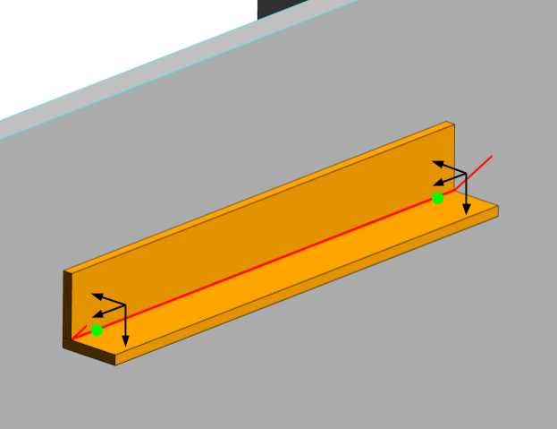
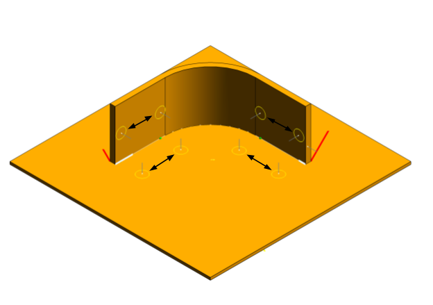
The first thing that Verbotics Weld will do is to create the calibration locations. These are points along the path where we would like to identify the offset - in 3D space to adjust for it. In this case we will put one at the start and one at the end. In Verbotics Weld each calibration location is signified by a green sphere.
The next thing Verbotics Weld will do is to determine what the touch directions at leach location should be. The touch directions are 3 orthogonal (at right angles to each other) directions such that the sensing actions will gain complete measurement of the 3D offset for that point. Typically Verbotics Weld will make one of those directions align with the weld path direction.
|
The calibration locations shown by the green circles and the calibration directions as shown by the black arrows for the simple fillet weld example. |
Next is to search for the best places to touch the workpiece. At this point we are expecting the workpiece to have a potential error. For example the position of this fillet weld assembly could differ by up to 10mm in any direction. If we are trying to touch a small feature, say like the edge of this plate, depending on the error, we may end up missing it completely. In some cases the feature we touch may also give a different result depending on what the error is, for example, in a curved part. To account for this we effectively are looking for a planar surface, that will give the same touch sense result no matter what the error is.
Once we have one direction found. We can use this information to improve the next. This is very useful for lap joints or other joins where there are smaller features to sense. In the case, we use the first two sensing results to update the position for the third sensing action which is on the side of the plate. More explanation about this process is in ‘finding sensing actions’.
|
The three sensing actions as shown in the Verbotic Weld viewer. The first two actions found are planar objects as shown by the circular error ring. The third sensing action relies on the offsets generated by the first two actions to prevent the third action from missing the plate. |
Once this is complete this code will be output to the robot and ready to run.
Uncalibrated path (top) vs the calibrated path (bottom) after the path calibration actions have been completed by the robot. |
Calibration Locations
The calibration locations are set to allow for linear interpolation between these locations. Verbotics Weld has some rules of where these are placed:
At the start and end of a weld.
Spaced at a maximum distance of 500mm along straight sections.
Spaced at 90 deg along curved sections.
Additionally Verbotics Weld will:
Only have a single location for weld lengths less than the replacement distance set.
Ignore curved sections at the start and end that are less than half the replacement distance set.
The sensing actions for each of these locations must be found and valid for the full calibration to be valid, otherwise the weld fails.
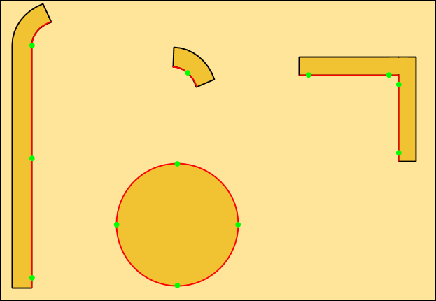
|
Top view of some parts on a plate showing the weld paths in red and the calibration locations in green. Left: The long straight section is split where an additional location has been added to the middle as this was greater than 500mm. Middle top: This short curved weld is less than the replacement distance. It only has a single calibration location in the middle. Middle bottom: This circle has calibration locations added every 90 deg. Right: There are two straight sections, calibration locations are added at the start and end of each. |
Finding Sensing Actions
At each calibration location, Verbotics Weld performs a search to find plane, line, and point calibration actions for the three dimensions that make up the complete sense action. Initially, planar surfaces that face the search direction are found. Where there is no previous search information known, the expected error could be in any of the 3 directions. One of these directions is the search direction which the robot is in the process of measuring, an error in the other two directions need to provide a very similar result, therefore requiring a plane.
|
The possible unknowns for the first search action. The part could be slightly higher/lower, or forward/backwards or a combination of both. The third unknown (left/right) is what we are sensing so this is not an issue. |
When searching for sense locations the planning algorithm will also ensure that the location is within the sensing replacement distance and the pose of the search position is similar to that of the weld at the calibration location. This means that we can account for some robot positional error, as long as the robot positional accuracy is acceptable between the sensing pose and the welding pose.
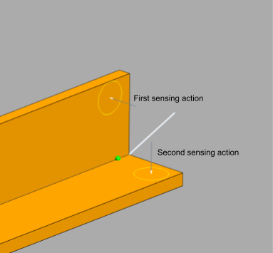
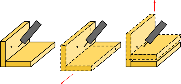
Once this search is complete, we now have some information about one of the directions. For the searches that follow, we can use this to reduce the possible unknown directions. For example, consider trying to sense the bottom edge of this part. If the part is slightly below where we expect, the wire will move over the top without contacting the plate resulting in an incorrect search. However, if we sense the top surface first, we can use this information to adjust where the second search is made, ensuring we are able to sense the plate edge.
|
Sensing the edge of a plate. Depending on the thickness of the edge and the overall error of the robotic system a calibration action planned here may result in the wire not contacting the plate. The left image shows the anticipated contact point, the right image shows one possible outcome with an error causing the plate to be lower than anticipated. |
|
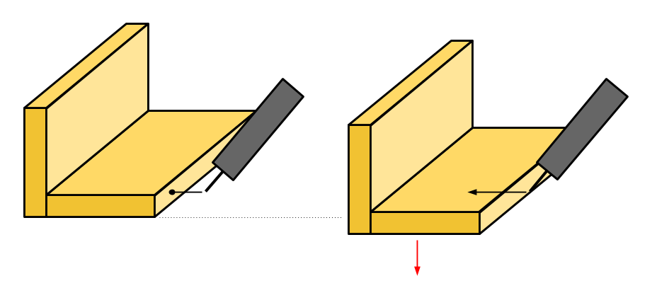
The second sensing action is made relative to the first. If the first sension action detects that the plate has been moved down, the second action will also be moved down to account for this allowing the plate edge to be used for sensing. |
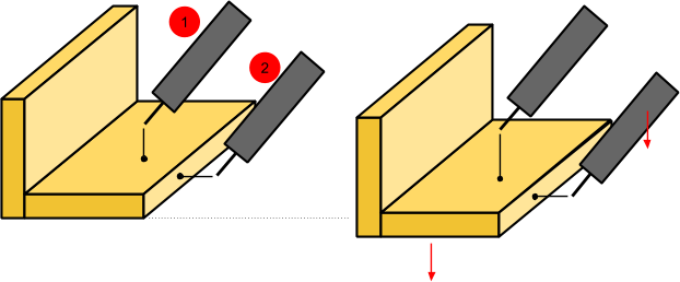
Effectively after the first search occurs, the error is only in two directions, one of which is the search direction. Therefore we are only searching for a line that will result in the same measurement value for the search action.
Finally once two directions are known we can begin to look for point objects as we now only have an unknown error in the search direction.
The key consideration for this is that the features in the model are accurate. With certain options, Verbotics Weld will use a part feature unrelated to the weld seam to calibrate the weld. If the distance between the feature used for sensing and the seam differs between the model and the real part, there will be a difference in the position of the weld seam.
|
A weld seam that uses the pate edge to calibrate the path position. On the real workpiece the bottom plate is longer than the same part in the CAD model. This will result in the calibrated path being moved to the wrong position (the dotted red line). |
Interpolation
We now have some locations with offsets. What happens in between these?
The routines that Verbotics supply for your robot will create a linear interpolation between these points. That is, it will look at the distance a point is between the calibration locations and make a linear adjustment based on that distance. This allows the robot to compensate for slight angular errors as well.
|
Path with angular misalignment. The Verbotics routines on the robot will linearly interpolate between the calibration locations. This enables compensation for angular misalignment between these calibration locations. |
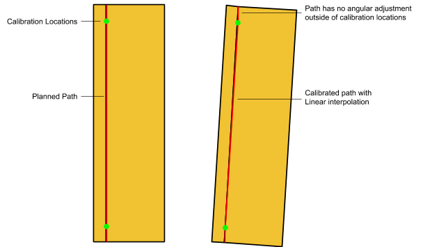
Linear interpolation also allows Verbotics Weld to compensate for other types of errors, for example if a part is slightly longer than expected.
Two-point and three-point calibration
In some cases it is not possible to sense all three directions. For example, if a weld ends part way down two right angle plates, the actual plate end may be too far away to provide meaningful sensing information. In these cases we ignore the third direction, if the third direction is aligned with the weld direction. This could result in the start or end of a weld starting along the parts a bit further. If this is a problem, Verbotics Weld has the option to force three-point sensing.
Other Search Considerations
With the search positions found we also need to consider the robot collision (with any possible error included), we need to make sure the robot can approach and retreat from that point without collision, and we need to ensure the robot can move between all the search points.
Optimisation
Optimisation is used to combine similar search actions. Consider a fillet weld with a small angular change in the middle of the weld. In this case the locations will be set at the start and end of each straight section. At the corner touch, there will be a redundant action where the base plate is sensed twice, once for each nearby location. It is not expected that these actions will create significantly different results so a single sensing action can be performed and applied to both locations.
After Verbotics Weld creates all the sensing actions. An optimisation routine is run to find similar actions that can be combined. This is looking for sensing actions which have the following properties:
Sensing directions are the same.
Sensing plane is equivalent.
The robot pose for each sensing action are similar.
Sensing points are within the replacement distance set.
|
Sensing actions for a weld with a curved section. The black arrows represent sensing actions that are candidates for being combined as they are in the same direction and sense the same planar face. |
Options
There are several sensing options available in Verbotics Weld. These are available in the calibration settings section of the weld settings widget.
|
Sensing options in Verbotics Weld. |
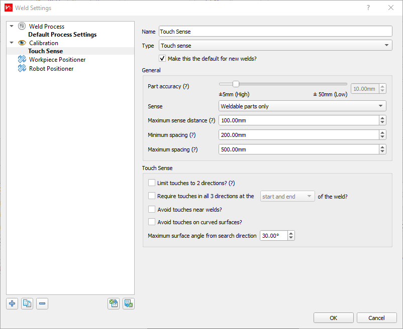
Part accuracy: This is the maximum amount of displacement error verbotics will use for determining which faces to sense.
Sense:
All parts - Use any parts even if they are set as non-weldable.
Weldable parts only - Only sense parts set as weldable.
Weld faces only - Only use the faces that make up the weld.
‘All parts’ will allow the planner to use all surfaces, even if they are part of the fixture or are not welded. Sometimes it is suitable to use simplified models for fixturing and in this case, the fixture should be set to non-weldable and the sensing option set to ‘weldable parts only’ or ‘weld faces only’
Verbotics will use faces that are not the faces directly adjacent to the weld for some sensing actions. This can lead to incorrect results if displacement between the faces that are being used for sensing differ between the model in Verbotics and the real-world parts. ‘Weld faces only’ should be used in this case.
Replacement distance: How far a sensing action can occur from a location.
Maximum Spacing: The maximum distance between two sensing points for straight sections.
Require touches in all 3 directions at the:
start and end
start only
end only
start or end Sets the locations for requiring 3 point sensing actions.
Avoid touches near welds: Will check that no touches will occur within 10mm of a weld. Useful to prevent sensing near already completed welds, or where parts may be tacked together. Will prevent sensing lap joints.
Avoid touches on curved surfaces: Will not use curved surfaces for sensing.