Weld Settings
Weld Process
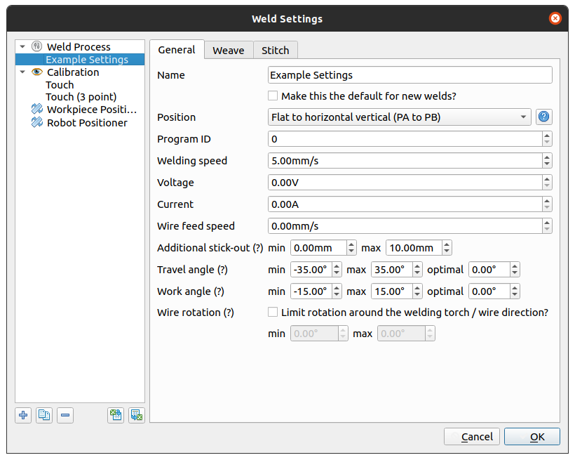
Name: The name of the weld setting.
Position: The position to perform the weld (e.g. downhand, vertical up). A workpiece positioner is required to orient the weld in the selected welding position. If there is no workpiece positioner, this setting will be disabled. See the Weld Position section for a description and diagram of each possible value.
Program ID: Sets the welding program in the
welddatafor ABB robots.Arc Start: For all other robots this is the text that will be placed in the arc start command. For Yaskawa robots ‘13’ will create the arc on instruction
ARCON ASF#(13). For Fanuc ‘1, 1’ will add the arc on instructionArc Start[1, 1]to the end of movement at the start of the weld.Arc End: For non-ABB robots. The text that will be placed in the arc end command. For Yaskawa ‘13’ will create the arc on instruction
ARCON AEF#(13). For Fanuc ‘1, 1’ will add the arc on instructionArc End[1, 1]to the end of movement at the end of the weld.Welding Speed: Sets the speed for welding.
Voltage: Only used in ABB robots to set the voltage in the output
seamdata.Current: Only used in ABB robots to set the current in the output
seamdata.Wire feed speed: Only used in ABB robots to set the wire feed speed in the output
seamdata.Additional stick-out: Amount of stick-out to use over the set TCP position.
Travel angle: The minimum, maximum, and optimum travel angle to use when planning welds. This is the equivalent to the push/drag angle. Negative values indicate a drag. The optimum value will be used as the ideal travel angle where possible. The minimum and maximum set the limit of the travel angle.
Work angle: The minimum, maximum, and optimum tilt angle to use when planning welds. A value of zero will bisect the two faces that formed the identified welds. The optimum value will be used as the ideal tilt angle where possible. The minimum and maximum set the limit of the tilt angle.
Wire Rotation: The minimum and maximum values of the wire rotation (angle between the welding torch travel direction and the weld direction). An angle of zero would always align the torch travel direction with the weld direction. By default, this is unconstrained.
Tip
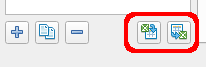
Weld settings can be imported and exported in order to share them more easily between projects.
Weave
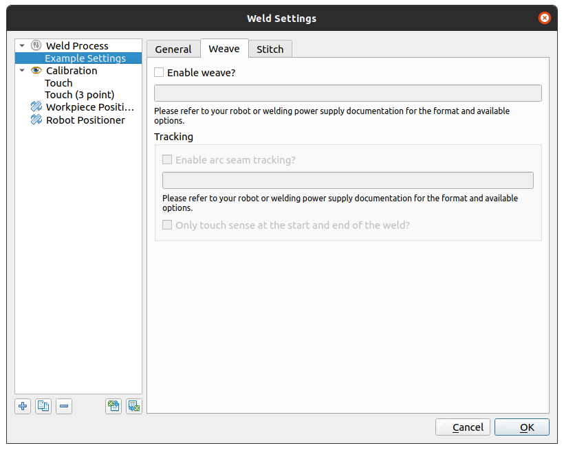
Enable weave? Will output the instructions to make the robot weave during welding if enabled. The textbox should be used to add in the weaving parameters to be sent to the robot.
For ABB this will be the
weavedatafor example[1,0,3,3,0,0.2,0,0.2,0,0,0,0,0,0,0]. For Yaskawa this will be the weaving file number e.g.3.Enable Tracking Will output the instructions to make the robot use seam tracking during welding. The textbox should be used to add in the weaving parameters to be sent to the robot.
For ABB this will be the
trackdatafor example[0,FALSE,10,[0,20,20,0,0,2,10,20,2],[0,0,0,0,0,0,0]]. For Yaskawa this will be the Comarc settings for exampleU/D=260 L/R=5.0.
Stitch
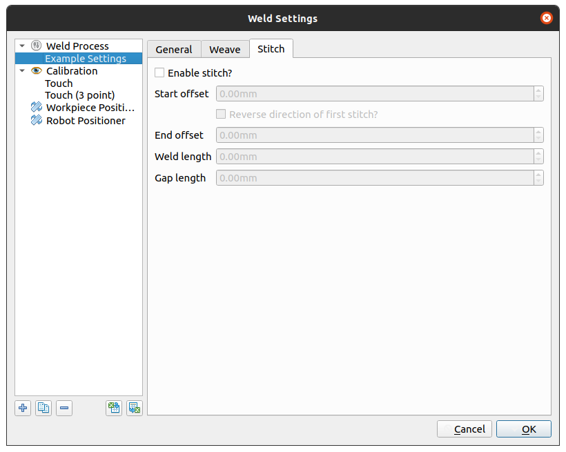
Enable stitch? Will create a weld with stitch pattern.
Start offset: The distance from the start of the weld to begin the first stitch.
Reverse direction of first stitch? Reverses the direction of the first stitch if enabled. Useful to reduce the amount of drag travel angle require to move from an inside corner.
End offset: The distance from the end of the weld to end of the last stitch.
Weld length: The length of each stitch segment.
Gap length: The target length of each gap segment. The gap will be adjusted for each weld such that the stitches have the full segment length depending on the overall length of the weld.
Weld Position
The Position value controls how the workpiece positioner is controlled relative to the weld. The possible values are shown below. Verbotics Weld will attempt to meet the desired weld position where possible within the ability of your workpiece positioner.
Value |
Diagram |
Description |
ISO 6947 |
|---|---|---|---|
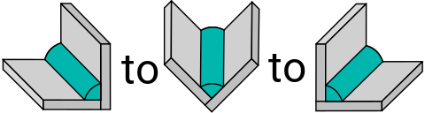
Flat to horizontal vertical |
|
Allows the weld position to transition freely between flat and horizontal vertical positions as required. The extents are based of the weld’s groove angle. This is the default value. |
PA to PB |
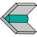
Flat |
|
Maintains the weld at the ideal flat / downhand position. |
PA |
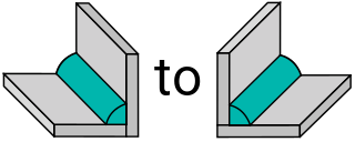
Horizontal vertical |
|
Maintains the weld at the ideal horizontal vertical position. |
PB |
Horizontal |
|
Maintains the weld at the ideal horizontal position. |
PC |
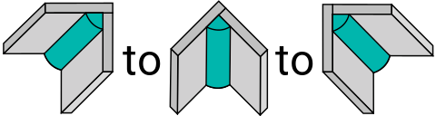
Overhead to horizontal overhead |
|
Allows the weld position to transition between the ideal overhead position and overhead horizontal position. Similarly to the “flat / horizontal vertical” setting, this is based on the weld’s groove angle. |
PD to PE |
Vertical Up |
|
Maintains the weld in the ideal vertical up position. |
PF |
Vertical Down |
|
Maintains the weld in the ideal vertical down position. |
PG |


Calibration Settings
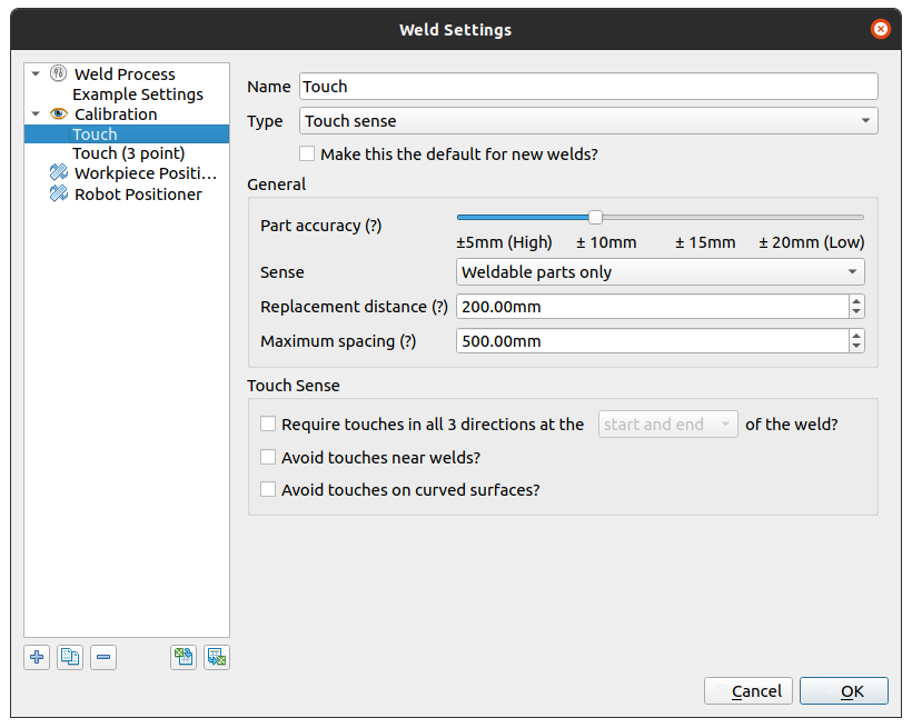
Name: The name of the calibration setting.
Type: The type of calibration used
Touch Sense: Use touch sense calibration
Laser 1D: Use 1D Laser touch sense
Make this the default for new welds? Configure new welds to automatically use these calibration settings by default
General
Part Accuracy: Sets the value to be used for the part accuracy (i.e. the maximum difference between the CAD model and real-world part). This setting changes the size of the uncertainty window when performing sensing. The calibration planner will take this into account for search actions.
Sense:
Weldable parts only Only senses parts that are enabled for welding. This can be useful for selectively preventing searching on certain parts.
Weld faces only Only touch senses on faces that are adjacent to welds. Note that this will not effect the sensing action that is in the weld direction.
Replacement Distance: Sets the maximum distance where a sense action will be used when planning. For example, if this is set to 50mm, The maximum distance that a sense can take place from the calibration location is 50mm.
Maximum Spacing: The maximum distance between two sense operations when touch sensing long straight paths. This allows better touch sense coverage for long welds, where calibration values are more likely to differ along the weld.
Touch Sense
Require touches in all 3 directions: An optional parameter to require a sensing action in the weld direction, This will improve the accuracy of the start / stop position of the weld but may not be possible depending on the geometry being welded. At the;
start and end: Require 3 direction touch sense at both the start and the end of the weld.
start or end only: Required a 3 direction touch sense at either the start or the end of the weld.
start only: Require 3 directions of touches only at the start of the weld.
end only: Require 3 directions of touches only at the end of the weld.
Avoid touches near welds? Controls whether the planner will avoid sensing locations where welds are in the project.
Avoid touches on curved surfaces? Curved surfaces may be prone to higher variability compared to flat surfaces. Use this option to avoid touch sensing curved surfaces.
Laser 1D
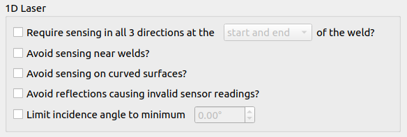
Laser 1D has two settings that are not shared with Touch Sense
Avoid reflections causing invalid sensor readings? When laser sensing, invalid sensor readings can occur is some situations due to reflection. This setting ignores these false positives by rejecting values surrounding those where a reflection could have occurred.
Limit incidence angle to minimum Limit the angle between the surface being sensed and the laser to be above the specified angle.
Workpiece positioner
Configure the behaviour of the workpiece positioner.
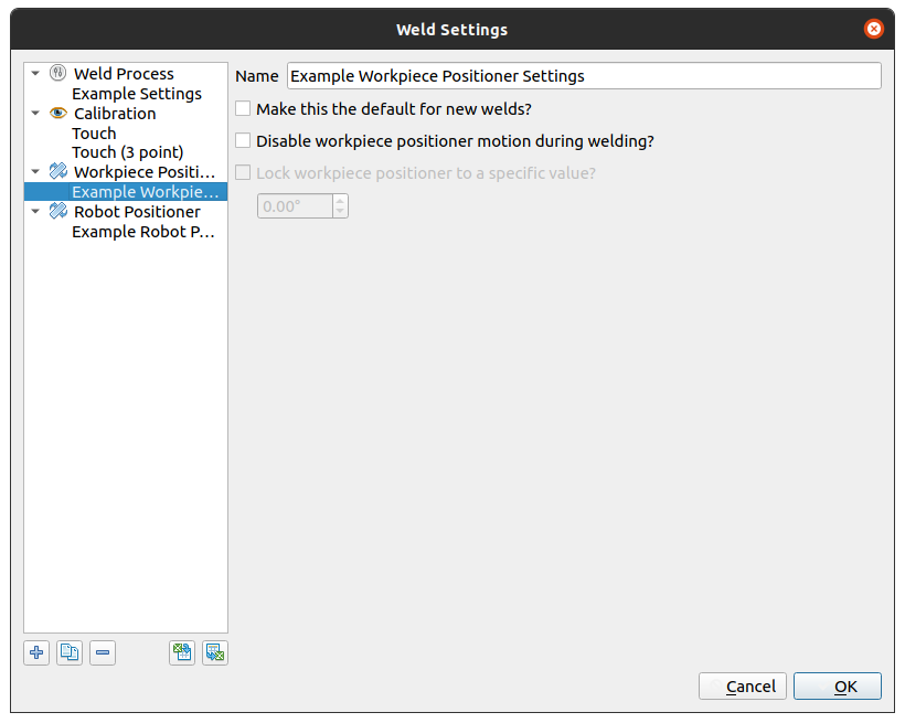
Make this the default for new welds? Configure new welds to automatically use these workpiece positioner settings
Disable workpiece positioner motion during welding? Will prevent the positioner from moving the workpiece during welding if enabled.
Lock workpiece positioner to a specific value: Sets the value(s) to set the workpiece positioner. This is useful if a specific workpiece pose is required for welding or the automatic algorithm in Verbotics Weld does not generate an acceptable solution. Can also speed up planning in some cases.
Robot Positioner
Configure the behaviour of the robot positioner.
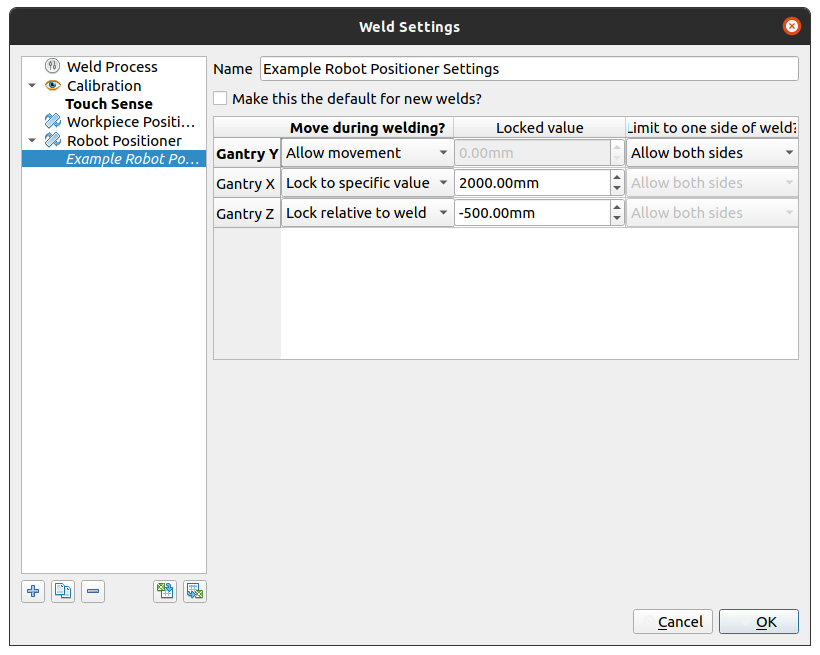
Make this the default for new welds? Configure new welds to automatically use these robot positioner settings
Configurable settings in the table influence the workpiece positioner axis with the name indicated in the first column. The configurable settings for each positioner axis are;
Move during welding? How the axis moves during welding
Allow movement allows the positioner axis to move freely within its limits
Do not move stops the positioner axis from moving during the weld
Lock to a specific value locks the axis to a specific value during the weld.
Lock relative to weld locks the positioner axis to value relative to the weld. There may be movement of the axis during the weld depending on the alignement bewteen the axis and the weld path. Configurable for Lock to specific value and Lock relative to weld. Sets the absolute or the relative to weld position of the locked value respectively.
Limit to one side of weld? Limit the selected positioner axis to only the positive or negative position relative to the weld. Can be useful for standardising the robot pose for a group of welds.