Laser Sensing
Laser sensing works in a similar method to touch sensing. However rather than having a physical wire that requires a circuit to form to detect contact, a laser is used where that same “contact” is detected when the distance measured by the laser is within a certain range.
Laser sensing has a number of advantages over touch sensing:
There is no wire to cut, avoiding the time taken to move and cut the wire.
The laser cannot be bent or damaged like a welding wire.
There is no problem with the wire moving between wire cutting and sensing.
It can be used to sense non-conductive surfaces such as plastic or painted parts and fixtures.
The main disadvantage is that there is another item to path find that can add a small amount of error to the overall path finding system, and it is not suitable for some reflective surfaces.
Verbotics Weld expects the laser to work as follows:
If the laser is out of range, the input should be low.
If the laser is above the threshold distance the input should be low.
If the laser is in range and below the threshold distance, the input is high.
Effectively the laser has a similar function as a virtual welding wire in this range.
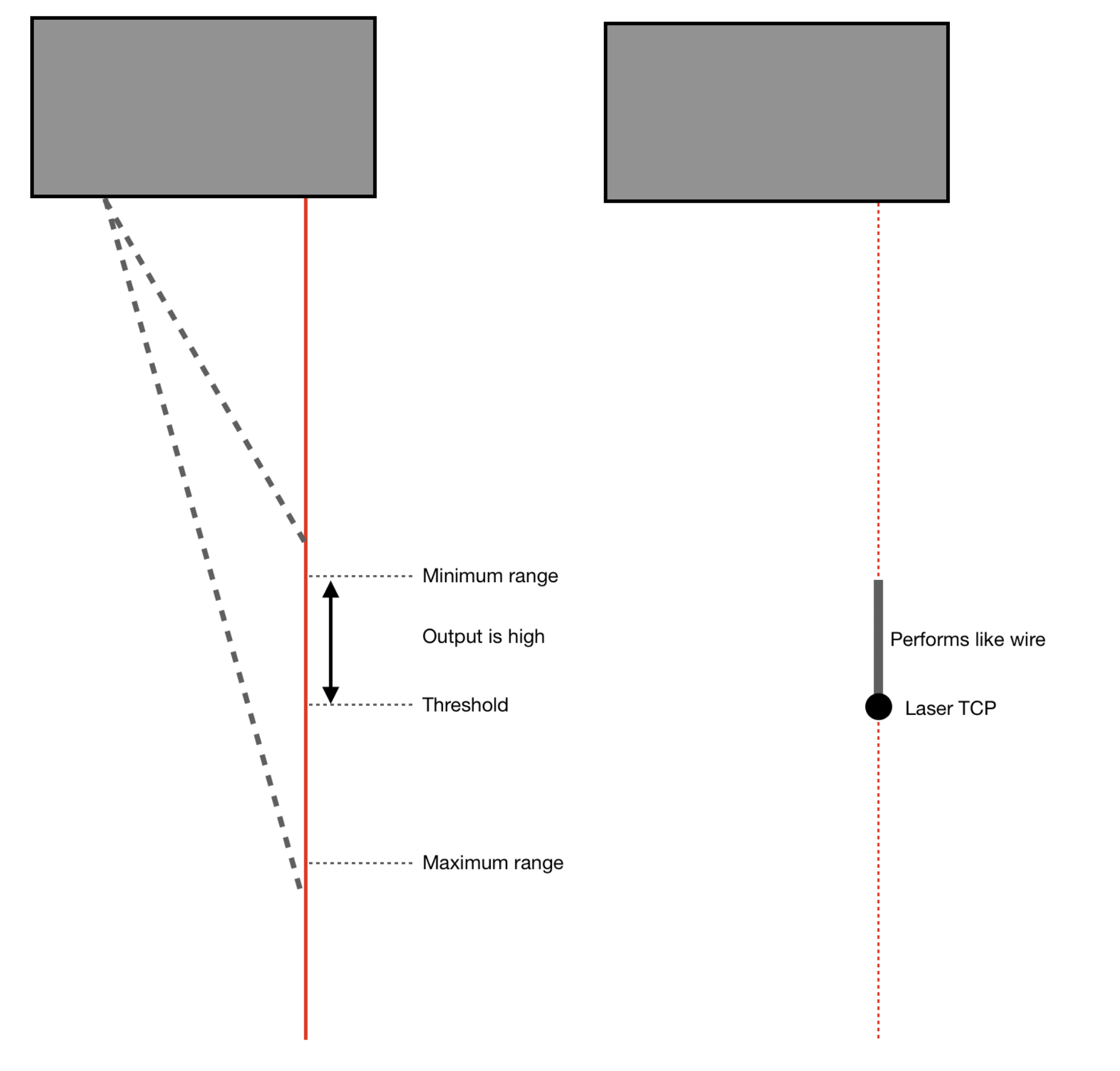
Laser sensing thresholds
This allows for the laser to be used as a wire tip, where the laser search is moved from above the threshold, to the threshold. Or in a side touch mode, where the laser is moved from out-of-range to within range and below the threshold.
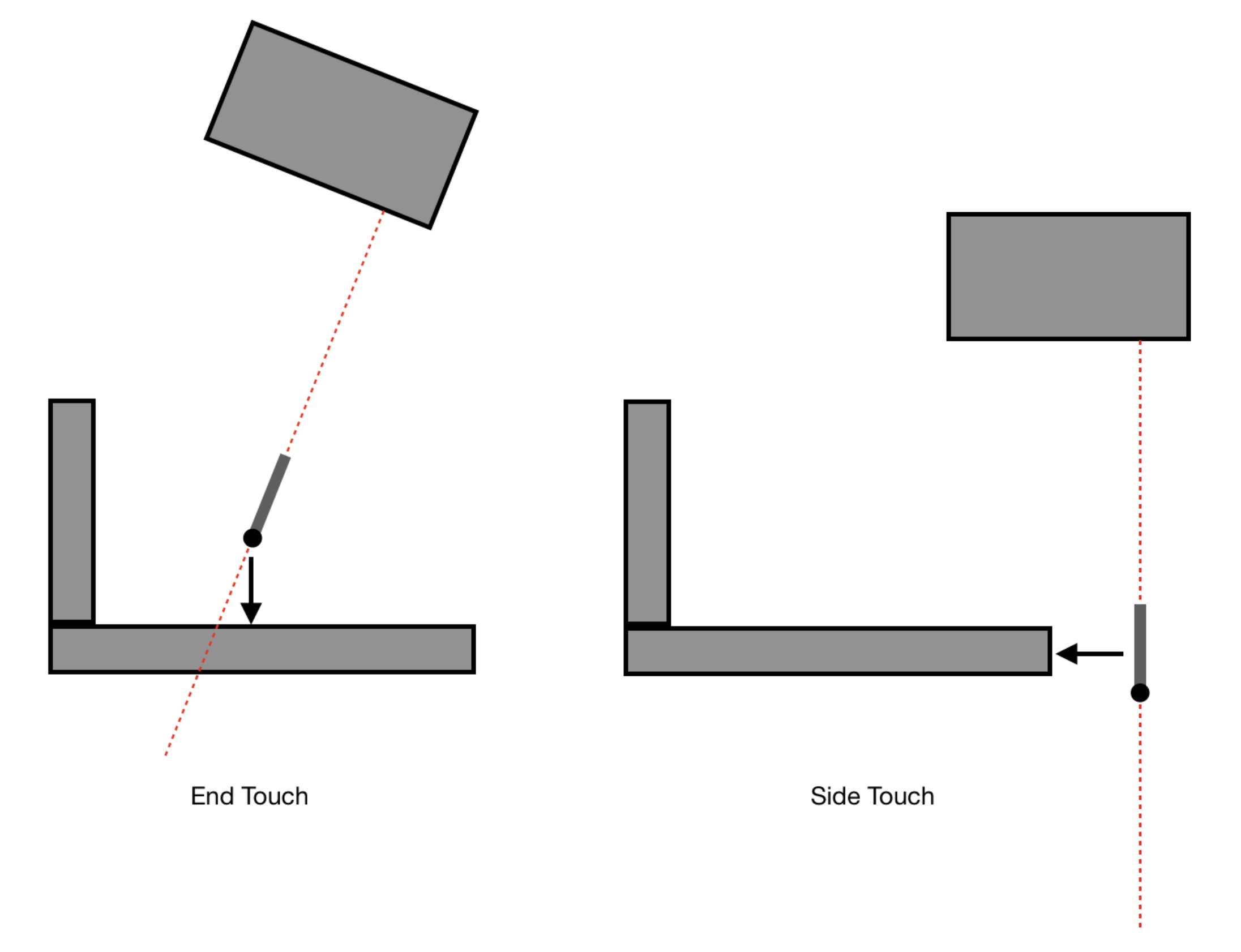
Laser sensing touch types
Calibration
To set your workcell up for laser sensing we need the following information along with a 3D model detailing how your laser is mounted to the robot. The Laser TCP is the furthest point where the output is expected to be high. The sensing range is the distance between the Laser TCP and where the output will be expected to be low due to being inside the minimum sensing distance of the sensor.
Parameter |
Recorded Value (Laser TCP) |
|---|---|
Laser TCP X (mm) |
|
Laser TCP Y (mm) |
|
Laser TCP Z (mm) |
|
Sensing Range (mm) |
For best results the sensing range should be at leat 50mm. The laser TCP should also be positioned such that it will not be obstructed by the welding nozzle. To teach the Laser TCP position:
Draw a small dot or make a small punch on a surface which you can point the laser at from multiple directions and which makes it easy to see when the laser is exactly on the dot (for example a small permanent marker dot).
Start the procedure on your robot to teach a new tool / TCP. It is important to use a different tool number / name than your welding TCP.
Place the laser on your reference dot at your desired sensing range, and zero the sensor at this position.
Note not all lasers have zero shift functionality. For other lasers, place the laser on the reference dot while it’s at the maximum detection distance as described above.
Record this as the first position in your robot’s TCP teaching procdure.
Continue your robots TCP teaching procedure (typically requires 3-6 measurements) as shown in the figure. For each measurement, ensure the laser is:
exactly on the reference dot
using a different position/orientation for the robot and sensor
the laser distance value is the same across all measurements (i.e. zero if your sensor supports zeroing / zero shift, or otherwise the maximum detection distance)
Provide the taught TCP XYZ values and sensing range to us.
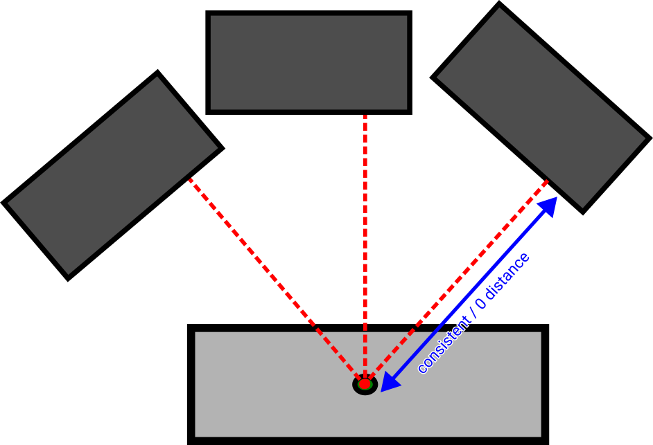
Measuring the reference dot from 3 distinct robot positions at the configured sensing range.