Planning Walkthrough
Tutorial
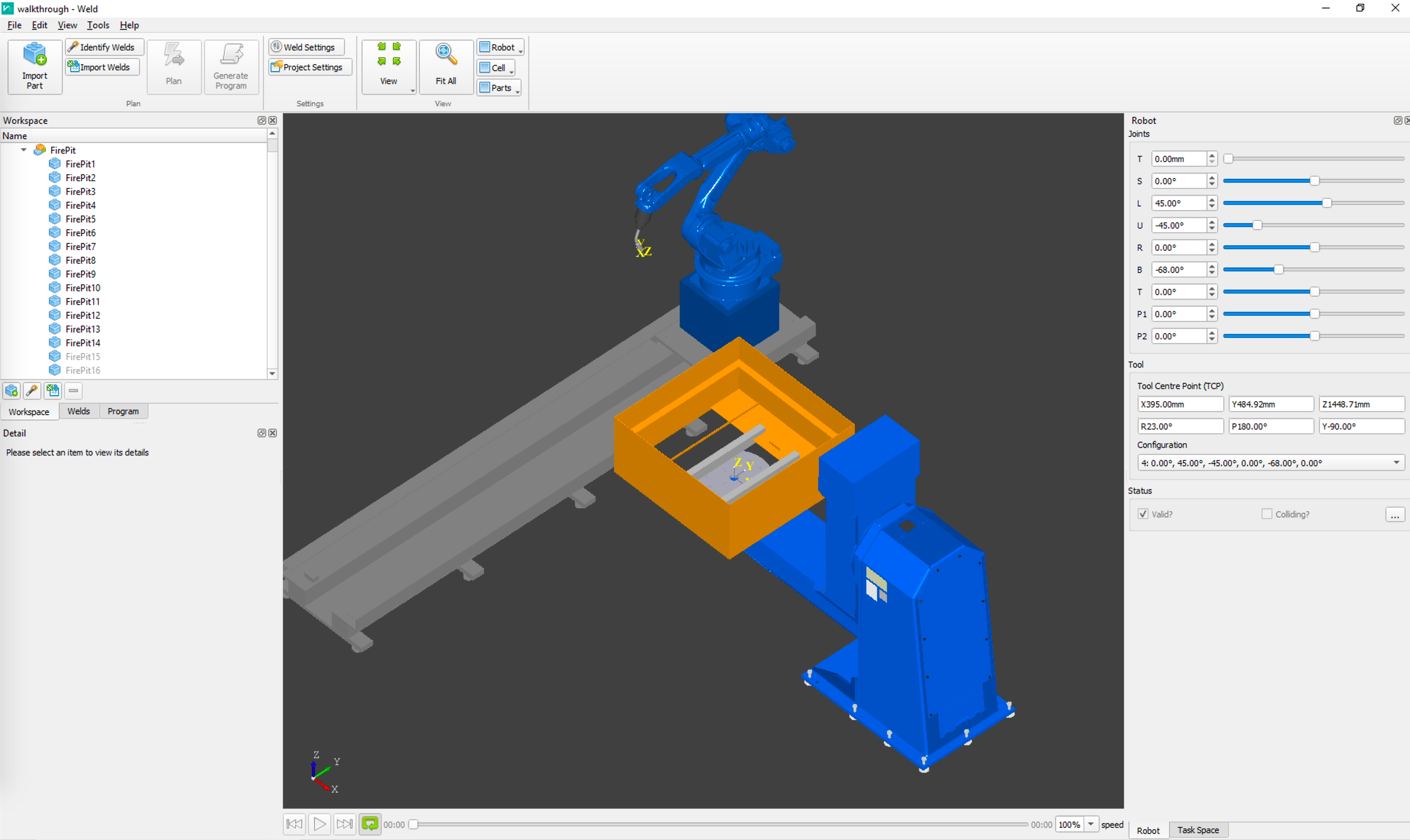
This tutorial shows how to generate a robotic welding program for a simple box component.
In Verbotics Weld there are many different ways to go about creating a weld program, this guide outlines the steps taken to create a program for an example part. It can be used as a reference guide for a general workflow to program a robot with Verbotics Weld.
Setup
This walkthrough is based on the “Yaskawa with positioner” example cell that can be downloaded from our website. To install Verbotics Weld and import the cell please see the Installation tutorial.
The example part used is a fire pit as shown below. Download the STEP model of the fire pit box assembly to your computer.
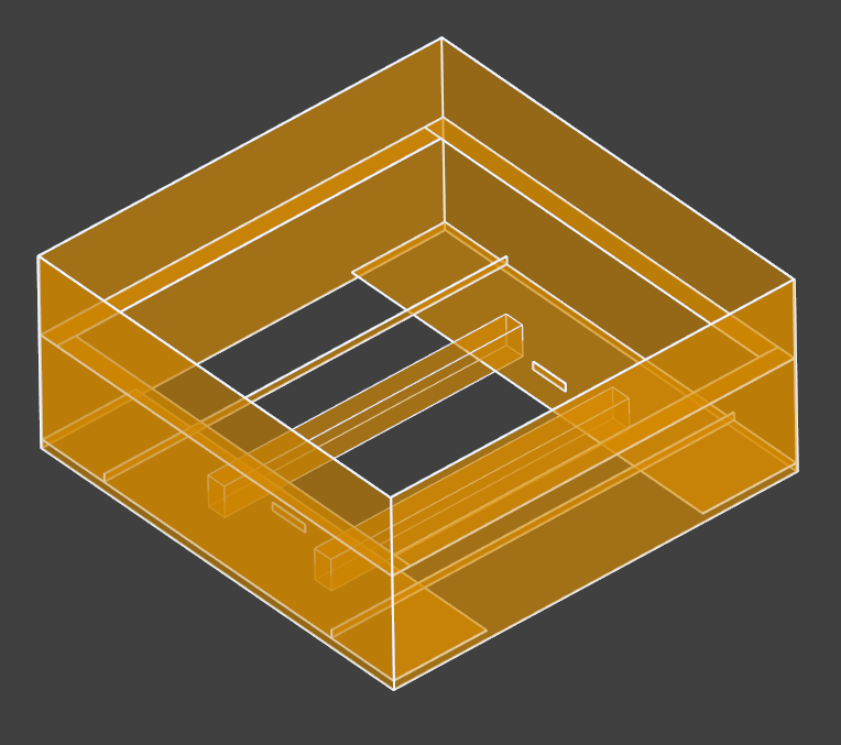
Example fire pit part
Project Creation
Step 1: Create an empty project
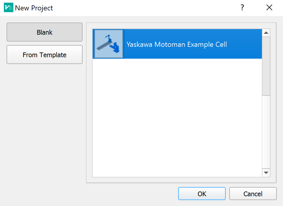
For this walkthrough we will be using the Yaskawa with positioner work cell. Click the “New Project” button and select the “Yaskawa Motoman Example Cell”.
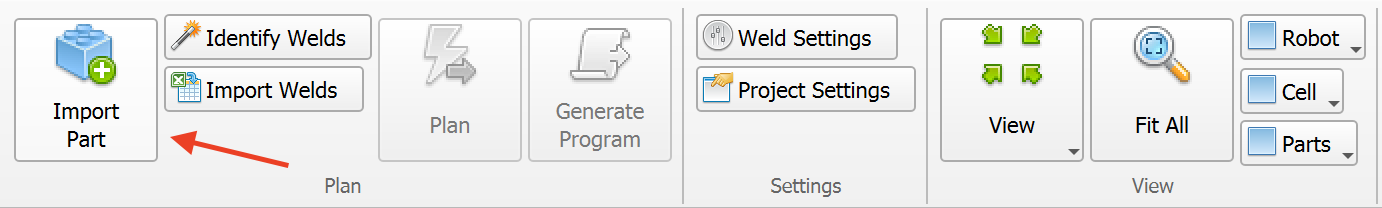
Step 2: Import part
Click the “Import Part” button in the ribbon and navigate to the directory where you have saved the example part. Select the part (STEP files are supported).
Step 3: Set fixturing parts as non-weldable
The “non-weldable” setting prevents the weld identification system from looking for welds in parts that are not weldable (such as fixturing), or welds between parts that have already been completed. In this project this part is attached to the workpiece positioner with two square sections that run along the bottom of the assembly. There are also some boxes that denote clamps. These parts will all be set to “non-weldable”.
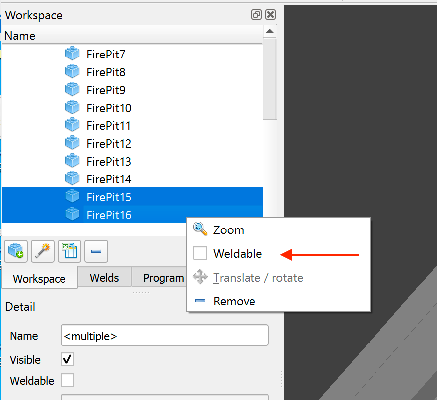
Select the part from the “Workspace” tab or click on the part in the viewer. Note that the CAD hierarchy can be expanded if parts are in sub-assemblies.
Disable the “Weldable” checkbox.
Parts that are set to ‘non-weldable’ are shown as grey in the viewer.
This section is complete. Your project should now look like this. You can save the project at this point by clicking ‘File’ > ‘Save’ and following the prompts.
Weld Detection
This section shows you how to use Verbotics Weld to automatically identify weld paths and directions from the CAD model. It does not require you to manually create each weld. For more details on weld detection please refer to the Weld Identification reference.
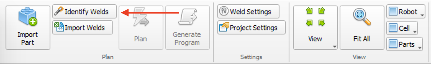
Click “Identify Welds” button in the ribbon.
Set the detection settings according to the table below.
Wait for welds to be detected.
Press the “Create Welds” button to add the welds to the project.
Weld detection distance |
1.0mm |
Combine welds closer than |
1.0mm |
Minimum weld length |
10.0mm |
Maximum immediate angle change |
60° |
Maximum total angle change |
1000° |
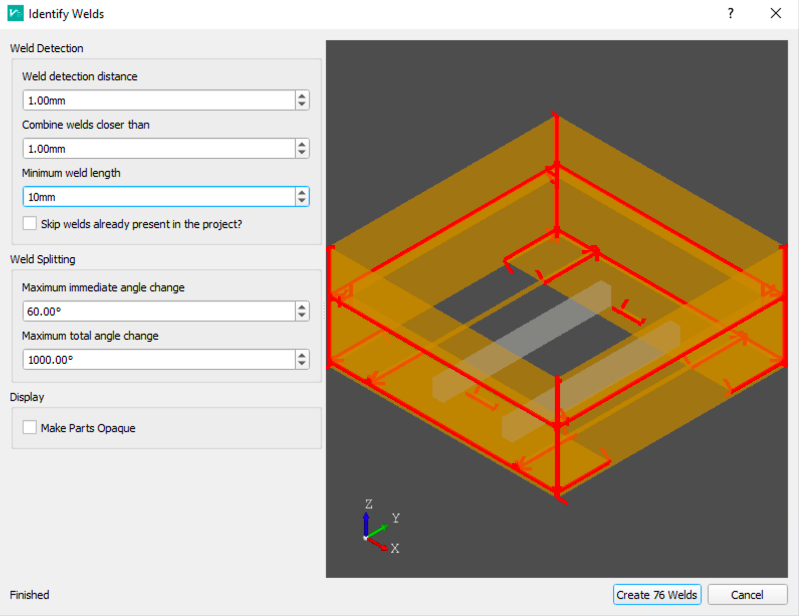
The weld identification dialog
Weld Settings
Step 1: Create weld settings
Weld settings in Verbotics Weld let our planning algorithms know how you would like your welds to be performed. In addition to typical settings such as the robot welding parameters, these settings also have the geometric limits of the process such as the wire stick-out, the push/drag (travel) angle, and the tilt (work) angle.
To create weld process settings:
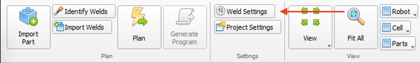
Click the “Weld Settings” button in the ribbon.
Add a new setting by clicking the “+” button.
Add the weld settings shown below. All other values can be left as their default values.
Name |
Test Settings |
Welding Speed |
10.0 mm/s |
Additional stick-out |
0mm to 10mm |
Travel angle |
-35° to 35° with optimal 10° |
Work angle |
-10° to 10° with optimal 0° |
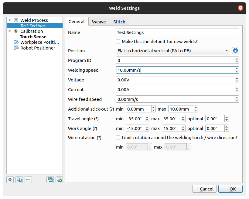
The weld settings dialog
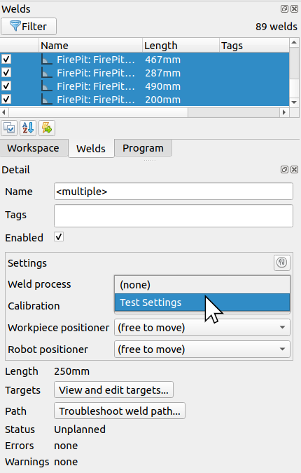
Step 2: Apply weld settings
Once you create the “Test Settings” weld settings, you can apply it to the welds in the project:
Go the Welds tab, and select all welds using Ctrl+A.
In the Detail area, select the “Test Settings” option in the Settings dropdown.
Remove Inaccessible Welds
Note
This section is optional. If you do not wish to remove inaccessible welds, please skip ahead to the Plan Welds section.
The weld identification process will detect welds on both the inside and outside of parts. The internal welds can be removed from the project to minimise clutter. This is done by checking if each weld is accessible to the robot. This step is optional, but is useful for geometry with closed off sections (e.g. rectangular hollow sections, closed boxes etc.).
Select all welds in the Welds tab, right click on them and click “Check Accessibility…”.
Wait for accessibility checker to complete, and accept the results.
Any inaccessible welds will have a grey icon next to their name.
Click Filter in the Welds tab and only select “Inaccessible” welds.
Review the results. Any welds that should not be deemed “Inaccessible” can be resolved by clearing the plan for that weld. To do this, right click on the weld and click “Clear Plan”.
Select all inaccessible welds, right click, and select “Remove Weld” to remove them from the project.
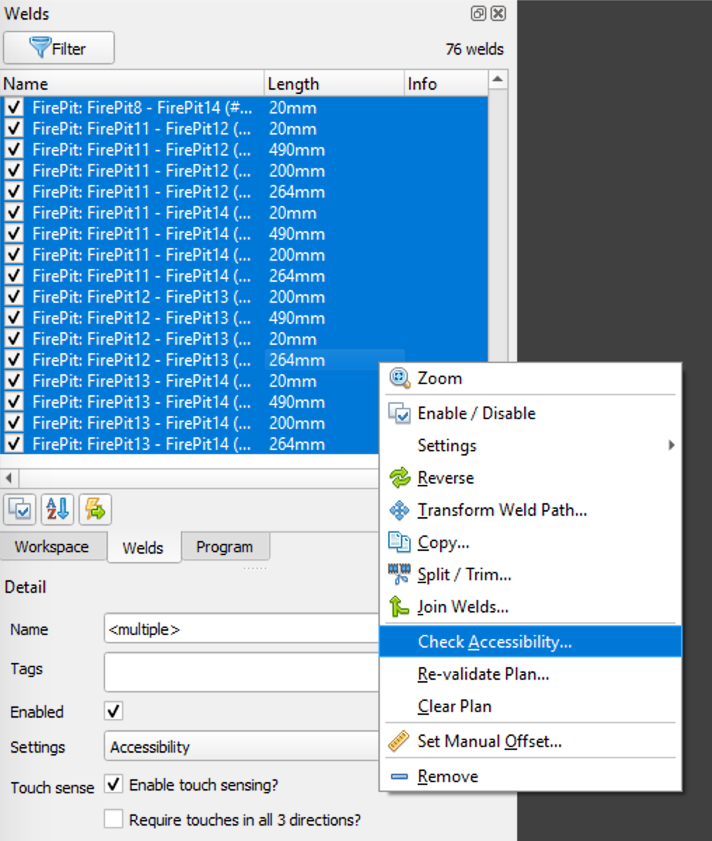
Step 1 select Check Accessibility
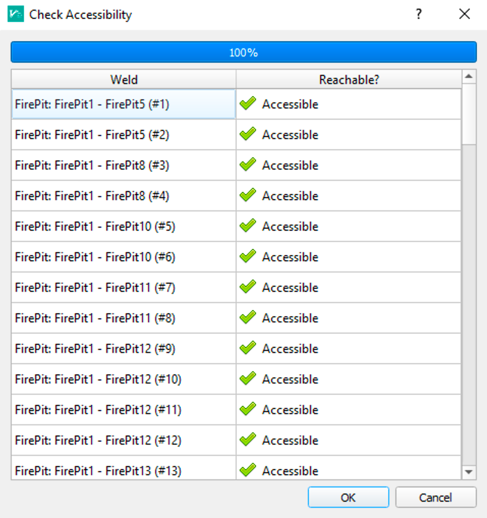
Step 2 the Check Accessibility dialog
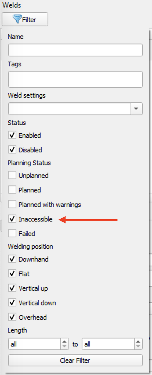
Step 4 filter for inaccessible welds
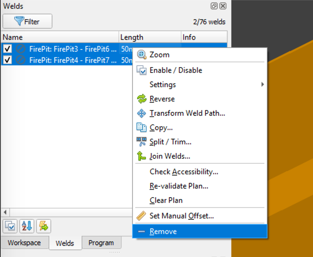
Step 6 remove welds
Plan Welds
Planning runs the Verbotics Weld planning algorithms that will attempt to generate the weld, calibration and motion paths. Our algorithms take into account collisions and robot kinematic limitations to automatically create these motions without the typical human effort required in typical offline programming packages.
Verbotics Weld uses probabilistic techniques to perform planning. This will mean you may get different results each time a weld is planned. For this reason we suggest trying to attempt planning 3-5 times in the case that a weld is not successfully planned in the first instance.
Click the Plan button in the ribbon.
Set the planning attempts to 5.
Click the Plan button in the dialog.
Wait for planning to complete (approximately 20 minutes depending on your computer performance).
Click OK when planning is complete to apply the results to the project.
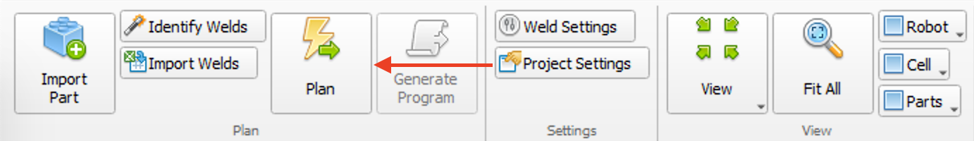
Step 1 click the Plan button

Step 2 the Plan dialog
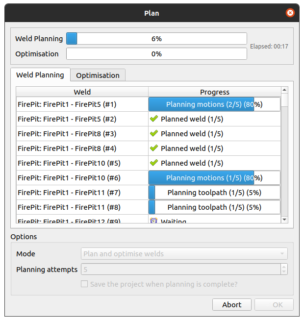
Step 4 waiting for planning to complete
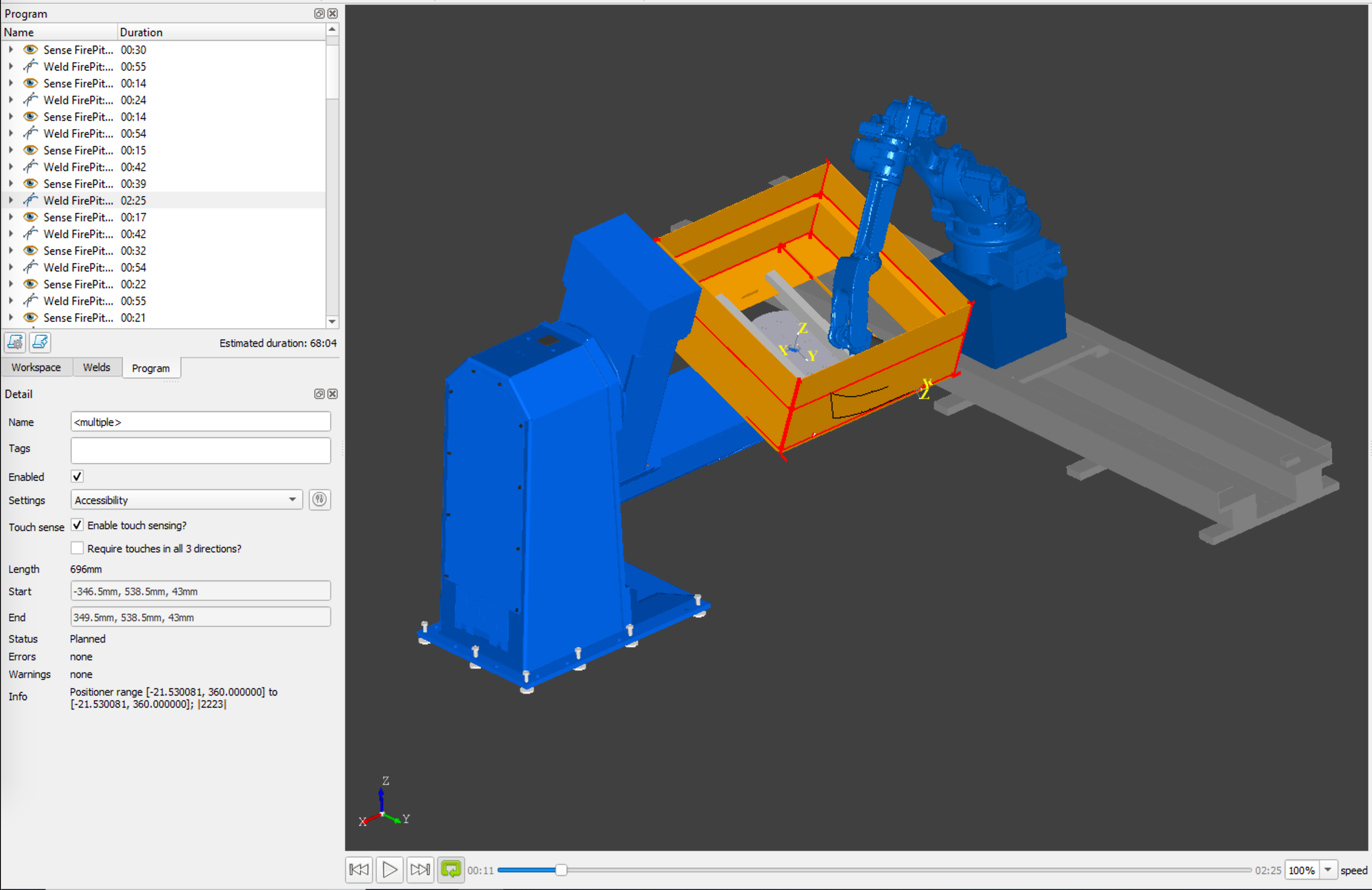
Simulate Paths
The motions created by the planner can be simulated in the viewer. From the Weld tab, each individual weld can be simulated, and in the Program tab the complete weld process can be simulated.
Click on an weld in the Weld tab, or a process in the Program tab to simulate it.
Use the simulation controls under the viewer to play and pause the simulation.
Generate Code
The final step is to generate code for your robot. In the trial version, code generation is not available. Please contact us if you would like to access sample code or discuss purchasing Verbotics Weld. For currently supported robot makes, please see the Supported Robots page.