Weld Identification
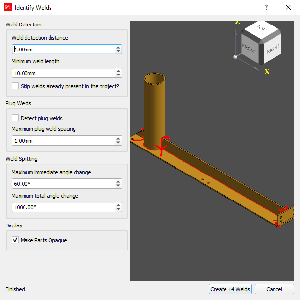
The “Identify Welds” dialog analyses your part CAD model to automatically identify where weld paths should be located, and the optimal wire position. This process can take a moderate amount of time for large or complex parts, as indicated by the progress bar in the bottom left of the dialog. Intermediate identification results will be shown in the 3D window, and you can click “OK” at any time to accept a partial result.
If you want to enable / disable a part within the identifier, you can click on the part. It will then switch colour and the identification will be re-started. You can also click on an identified weld to prevent it from being created.
The weld identification dialog has a number of options available to control how welds are automatically identified from the CAD model.
Weld Identification Options
Weld Detection Distance
From each face of the CAD model, this controls how far to check for intersecting faces that may produce a weld. A value of zero will require parts to be intersecting for welds to be identified. If parts are drawn with gaps between them, and welds should be identified between those parts, a value high enough to span at least half the gap should be used. For example, if a butt weld is drawn with a 3mm gap (for example, to allow a full penetration weld), a value gerater than 1.5mm should be used to identify a weld in that location.
Default Value: 1mm
Minimum Weld Length
The minimum weld length that should be considered to be a weld. Prevents the weld detection from creating small welds where they are not required.
Default Value: 5mm
Skip Welds Already Present in the Project?
If enabled, this will not add any detected welds that are already in the project. These will be drawn as thin black lines in the Weld Detection dialog. This is useful when identifying welds with different settings to avoid adding duplicates.
Default Value: disabled
Plug Weld Options
Detect plug welds
If enabled, suitable locations for a plug weld will be identified. These welds will appear parallel to the centre of suitable spacing for the plug weld.
Default Value: disabled
Maximum plug weld spacing
The maximum distance between edges surrounding a space in which a plug weld is permissible. Any edges further apart than this value will not have plug welds detected between them.
Default Value: 10mm
Weld Splitting
Maximum immediate angle change
The maximum angle change between two consecutive points in a weld. This is calculated with both the change in nominal wire direction, and the change in path direction. Typically this means that a weld turning a 90° corner at the end of a plate will have an angle change of 180° between the points at the corner.
Smaller values will split welds at corners such as this, larger values can be used to allow the weld path to move around these corners and prevent a weld start/stop at the corner. Welds around corners can create some difficulties with planning.
Default Value: 45°
Maximum total angle change
The maximum angle change along the entire weld. This is calculated with both the change in nominal wire direction, and the change in path direction. Typically this means that a weld turning a 90° corner at the end of a plate will have an angle change of 180° between the points at the corner. This is useful to limit the size of circular welds to smaller sections if it will be difficult to plan the complete circular path.
Default Value: 360°