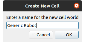
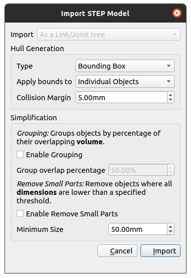
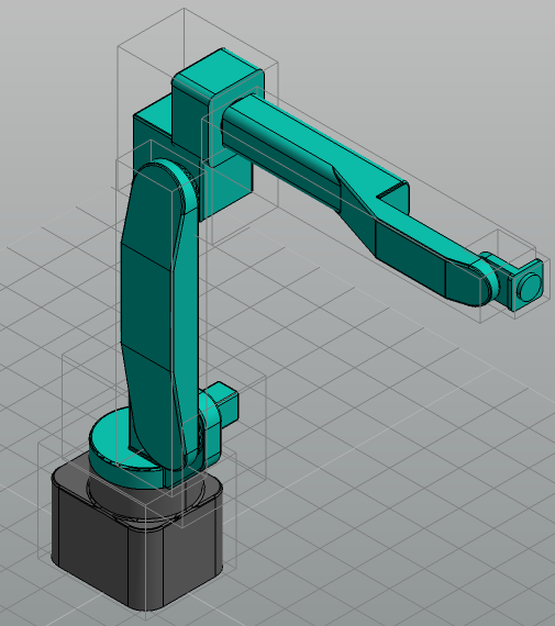
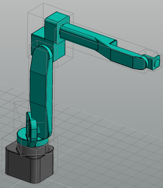
Often the necessary components for the construction of a workcell are not present in the preset library, and need to be constructed from scratch. Cell Editor is able to import STEP files and URDF files from ROS Packages to assist with the construction of these work cells. This tutorial will outline this process; from constructing a robot from a STEP file in Cell Editor to simulating the robot in Weld.
Currently, our imported STEP file is sitting in the workcell world, with the same structure as it would have originally had when exported from the CAD software where it was created. In this instance, all of the joints (and links) share one global parent transformation (robotv2_joint). We need to convert this series of ‘flat’ transformations to local transforms from one link to another.
Without doing this, each link would have a transformation that was independent of the previous joint. When one joint is moved, the rest of the robot would not follow suit.
We can demonstrate the necessity for this in URDF as a generalized format (and one which is used by Cell Editor) by attempting to change our joints now, without restructuring our transform heirarchy.
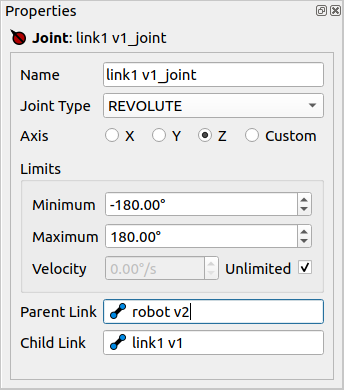
Select or use the Find feature to locate link1v1_joint. This will be the first joint in our robot.
Using the Properties panel, set the Joint Type to ‘REVOLUTE’
There are three types of joint supported by Cell Editor and Verbotics Weld.
Fixed joints are responsible for simply holding transformations. They have a parent, a child and an origin. Revolute joints are the same as Fixed joints, except they rotate around one of their axis. Prismatic joints are the same as Fixed joints, except instead they translate along one of their axis.
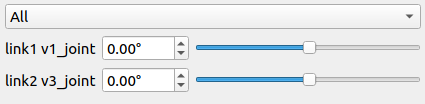
Notice the Robots widget on the right-hand side of the screen. You may need to click the Robots tab at the bottom of the pane. There is now a slider representing the new revolute joint. This joint can now be assigned a joint value.
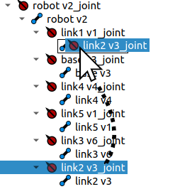
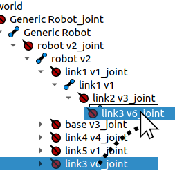
Reset the joint value of the slider back to 0.00° by entering it into the number field next to the slider. In the URDF widget, drag link2v3_joint onto link1v1 to set it as a child.
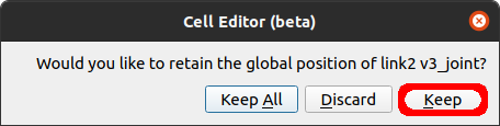
In the dialog that appears, choose to Keep the global transform of this link.
Warning
Make sure you have reset the joint value as described in this step. Otherwhise, the ‘Keep’ option we selected will result in the subsequent joint being tied to its current position relative to the previous joint!
Tip
If you make a mistake, you can always hit Ctrl+Z (Command+Z on Mac) to go back.
Once again, try jogging the robot using the Robot widget. This time, link2v3_joint and its children will follow along as we intend.
Now we are aware that the structure of the document affects the behaviour of the links and joints in the workcell, we are ready to begin building our robot. You probably already have a feel for how we would go about doing this.
Ensure that in the Robot widget, all modifiable joint values are set to their default value (0.00°)
Begin dragging subsequent links to form the robot such that subsequent links are children of their parent links. For all the below operations, when prompted select Keep when asked whether to retain their global transformation.
Expand link2v3_joint, then drag link3v6_joint onto link2v3
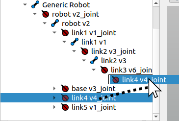
Expand link2v3_joint, then drag link4v4_joint onto link3v6
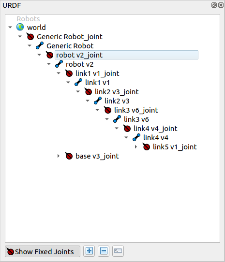
Continue in the same fashion for the next joint, dragging link5v1_joint onto link4v4
Cell Editor is a tool to easily create kinematic models. Having a kinematic model allows us to derive end-effector position from the joint values (forward kinematics) or joint values from the end effector position (inverse kinematics). Verbotics Weld uses the kinematic model to plan robot motions for offline weld programming.
Our robot is coming along very well. In this step, we will continue to set up the joints on the robot. As in the Structuring the Document step, we are going to continue setting types for joints to control how they move their respective links on the robot.
Using the URDF widget or the Find (Ctrl+F) feature, find link2v3_joint and select it.
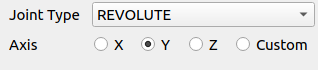
In the properties panel, change the type of the joint to REVOLUTE
Using the radio buttons in the properties panel, set the Axis of the joint to Y
Notice that the joint now appears on the Robot widget. Drag the slider to see how modifying the joint value affects the robot
You may have noticed that the joint can go 180° either direction of where it started. In our case, this means the robot is moving outside of where it would be possible. This is where configuring joint limits comes in handy, to make sure the robot is unable to move outside its physical limits.
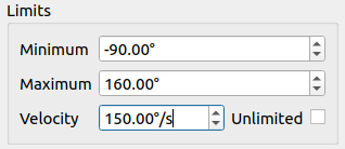
Set the joint limits. In the properties panel, inside the limits group, set Minimum to -90.00° and Maximum to 160.00°.
Uncheck the Unlimited velocity checkbox. Set the Velocity limit to 150.00°/s
Tip
Setting joint limits can significantly improve planning performance and/or feasibility by decreasing the size of the problem space.
Continue setting up the remaining joints to finalize the kinematic model.
Change link3v6_joint to be a REVOLUTE joint. Set its Axis to Y and its limits as follows;
Minimum
-90.00°
Maximum
90.00°
Velocity
150.00°/s
Change link4v4_joint to be a REVOLUTE joint.
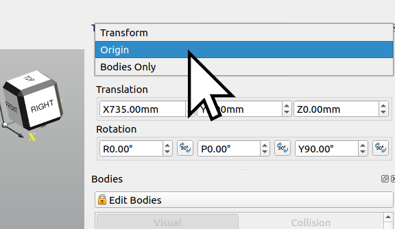
For this joint to behave properly with weld, we need to set this joint to be directly above the previous joint. To do this without changing the position of the visible bodies, we are going to use Origin Mode. Using the transform widget in Origin mode, set the X to 0.00mm
Select link5v1_joint. Note that in the case of this joint, we are going to need to modify the joint origin. With the current origin, Weld will be unable to solve the 6-DOF kinematic model we have provided. To fix this, we will change the origin of the joint such that X is pointing forwards and Z is pointing up.
Using the Transform widget, change the transform type to Origin
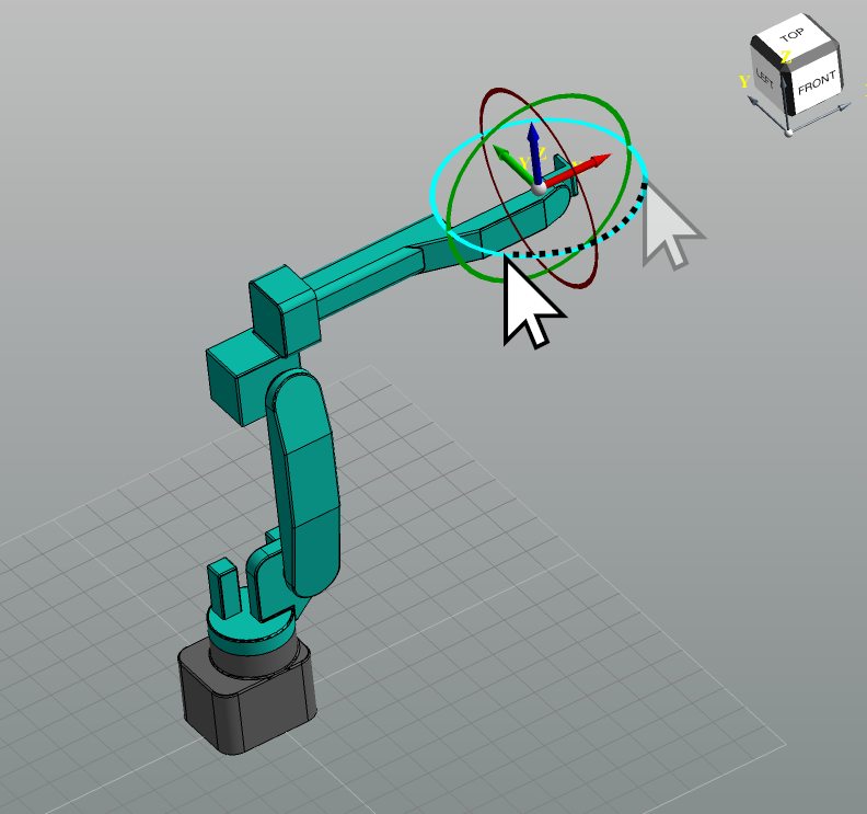
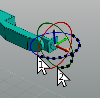
Using the toolbar above the viewport, change the snap angle to 90.0°. Click to enable the magnet icon to enable snapping.
As you may have already guessed, this process can be applied to any manufacturer robot model imported into Cell Editor.
Now that we have made sure out Robot is structure correctly in Cell Editor from the CAD model, our next step is the business end of the robot. Normally, a standard torch can be imported from the presets selection. In this guide, we will use the Body Editor to create our own torch.
Create a sixth link. This link is responsible for rotating the torch
Select link5v1
Go to the ribbon menu and switch to the Tools tab. Press Add Fixed Link
In the name field that appears, name the link “link6” and hit Ok
Notice that this feature has created a new joint automatically to locate link6. Select this joint, named link6_joint
With the joint selected, set the joint to be a REVOLUTE joint. Set its Axis to X and the limits as follows;
Minimum
-360.00°
Maximum
360.00°
Velocity
150.00°/s
Create the flange link.
Go to the ribbon menu and switch to the Tools tab. Press Add Fixed Link
In the name field that appears, name the link “flange_link” and hit Ok
Using the Transform widget, move the link 95.00mm along the X axis.
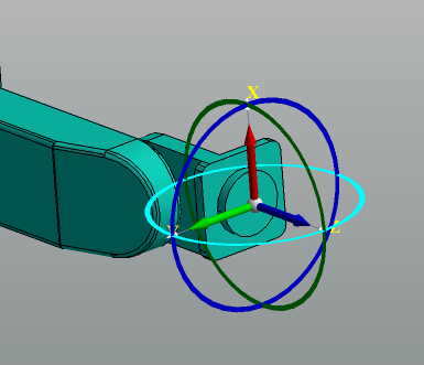
This link is going to need to be rotated such that the Z-Axis points forwards. With snap on and the snap angle set to 90.00°, rotate the joint in Origin mode by 180° along the Z-Axis, then 90° along the X-Axis. You should end up with something similar to the second image below.
Step 5: rotate the origin to point the correct direction
Create the torch. In our instance, we are going to create a simple torch out of primitives.
Create a new Fixed Link called torch_link by selecting flange_link and pressing Add Fixed Link
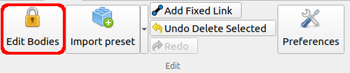
In the tools menu on the ribbon, press the Edit Bodies button, with the lock icon beside it.
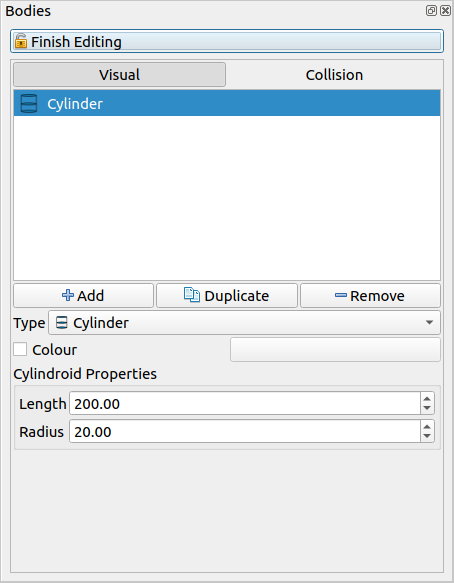
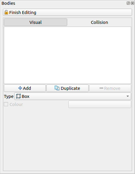
Activation of the Edit Bodies icon enables Body Mode. Down the bottom left of the screen, you will see the Bodies widget. This widget can be used to modify the bodies attached to links.
Create an example torch. Click +Add under the bodies list in the bodies widget, on the Visual tab. Change the body type to ‘Cylinder’. Set the following values;
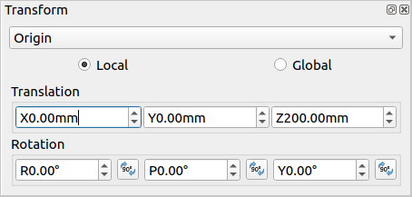
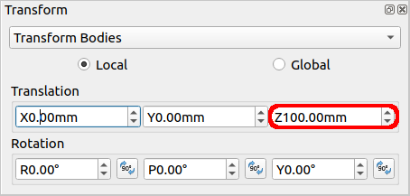
Use the Transform widget to move the cylinder into place. We are going to sit the cylinder directly onto this link origin. To do this, set the Z to 100.00mm
Step 5: Set the Z translation of this body to 100.00mm
Tip
The two tabs on the Body widget represent Visual and Collision bodies. Visual bodies are not used for planning in Weld. They are used as a guide for creating collision bodies, or to model the actual look of the workcell. Collision bodies are important for planning, but not so important visually.