1. Planning Walkthrough
Tutorial
This tutorial shows how to generate a robotic welding program for a fire pit assembly.
In Verbotics Weld there are many different ways to go about creating a weld program, this guide outlines the steps taken to create a program for an example part. It can be used as a reference guide for a general workflow to program a robot with Verbotics Weld.
Prerequisites and Resources
This tutorial uses the Example Yaskawa Motoman with Skyhook cell available to download in the new project menu. To install Verbotics Weld see the Installation tutorial.
Download the Example Part
This tutorial uses a fire pit workpiece assembly. Download it before you start.
⬇ Download Fire Pit STEP ModelVideo Tutorial
Step by Step Guide
Step 1: Preparing a New Project
For this walkthrough we will be using the Example Yaskawa Motoman with Skyhook workcell. Click the New Project button to open the workcell selection menu. To see example cells, ensure the Show examples? checkbox is enabled, then download and select the Example Yaskawa Motoman with Skyhook.
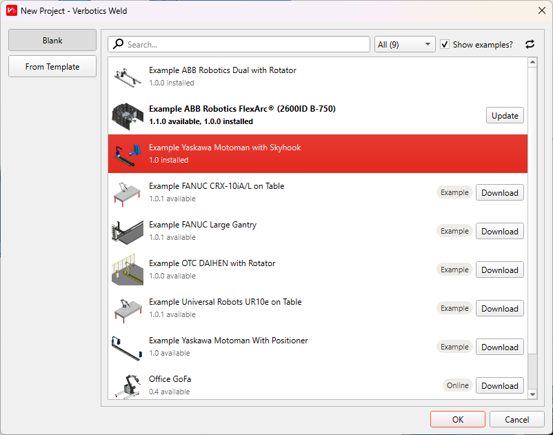
New Project Dialogue
Importing parts
Click the Import Part button in the ribbon and navigate to the directory where you have saved the example part. Select the part (STEP files are supported).

Import Part Button
Note
If you import a part and need to move it, you can right click on it and select “Translate / rotate”. See Transform Parts and Welds for more details.
Setting fixture parts as non-weldable
The weldable / non-weldable setting prevents the weld identification system from looking for welds in parts that are not weldable (such as fixturing), or welds between parts that have already been completed. In this project, the fire pit is attached to the workpiece positioner using a jig made up of 6 parts. These parts need to be selected and set to non-weldable, which are shown as grey in the viewer.
Select the parts from the “Workspace” tab or click on the part in the viewer. Note that the CAD hierarchy can be expanded if parts are in sub-assemblies.
Disable the
Weldablecheckbox.
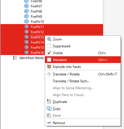
Not Weldable Option
If done correctly, the project should now look similar to the image shown below. You can save the project at this point by clicking File > Save.
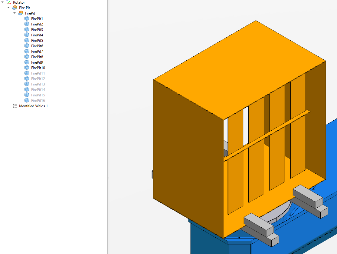
Completed Part Setup
Step 2: Weld Detection
This section shows you how to use Verbotics Weld to automatically identify weld paths and directions from the CAD model. It does not require you to manually create each weld. For more details on weld detection please refer to the Weld Identification reference.

Identify Welds Button
Click
Identify Weldsbutton in the ribbon.Leave the options at their defaults (shown in the table below).
Wait for welds to be detected.
Press the
Add Weldsbutton to add the welds to the project (the button label shows how many welds were found).
Weld detection distance |
1.0mm |
Minimum weld length |
10.0mm |
Maximum immediate angle change |
45° |
Maximum total angle change |
360° |
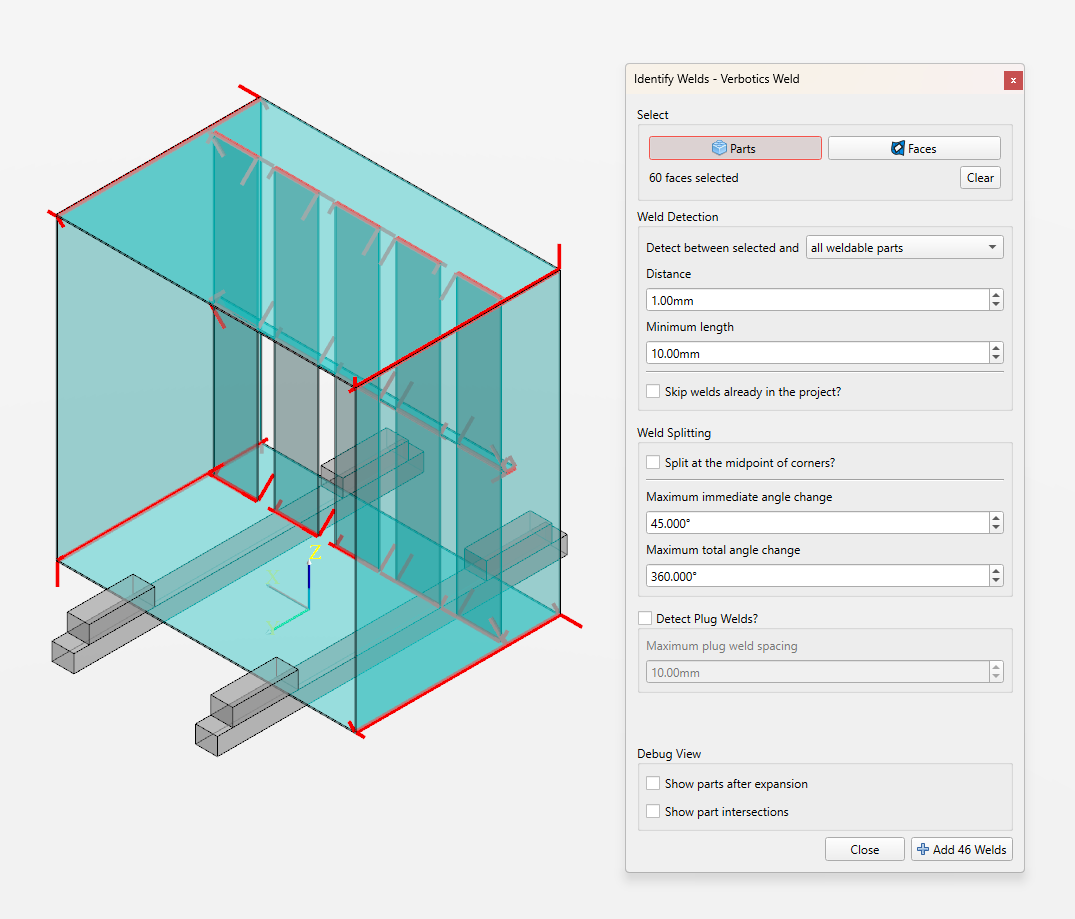
The weld identification dialog
Step 3: Adjusting the Weld Settings
Create weld settings
Weld settings in Verbotics Weld let our planning algorithms know how you would like your welds to be performed. In addition to typical settings such as the robot welding parameters, these settings also have the torch limits of the process such as the stick-out, travel, and work angle.

Weld Settings Button
To create/adjust weld process settings:
Click the
Weld Settingsbutton in the ribbon.Select the pre-existing Default Process Settings to edit.
Set the optimal Travel Angle to 10°. This will influence the planner to aim for a 10° push angle where possible when welding.
All other values should be left as their default values.
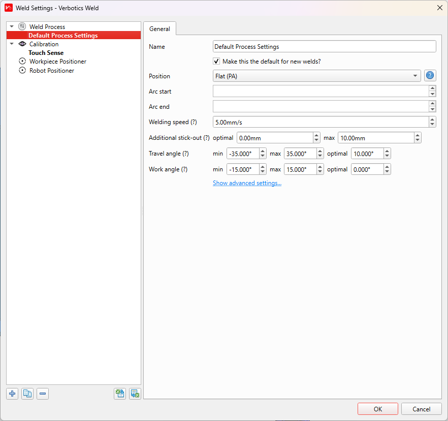
The weld settings dialog
Note
You can create multiple instances of weld settings by using the + symbol at the bottom of the Weld Settings menu. In most projects, it is common to have multiple settings to accommodate part variation.
Step 4: Preparing and Planning Welds
Plan Welds
Planning runs the Verbotics Weld planning algorithms that will attempt to generate the weld, path finding and motion paths. Our algorithms take into account collisions and robot kinematic limitations to automatically create these motions without the typical human effort required in typical offline programming packages.
Verbotics Weld uses probabilistic techniques to perform planning. This will mean you may get different results each time a weld is planned. For this reason we suggest trying to attempt planning 3-5 times in the case that a weld is not successfully planned in the first instance.
Click the
Planbutton in the ribbon.Click the
Planbutton in the dialog.Wait for planning to complete (approximately 1-2 minutes depending on your computer performance).
Click
OKwhen planning is complete to apply the results to the project.

Plan button
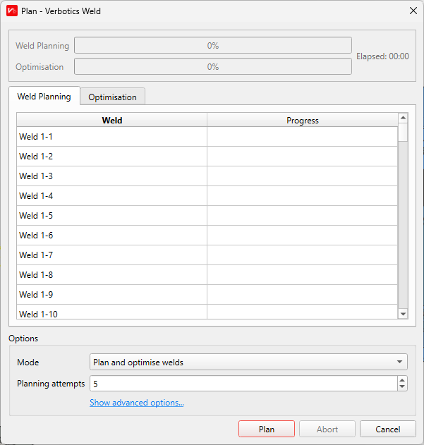
Plan Welds dialog
Step 5: Simulation and Code Generation
Simulating a Weld Program
The motions created by the planner can be simulated in the viewer. From the Weld tab, each individual weld can be simulated, and in the Program tab the complete weld process can be simulated.
Select a weld in the Weld tab, or a program step in the Program tab.
Use the simulation controls under the viewer to
playandpausethe simulation.
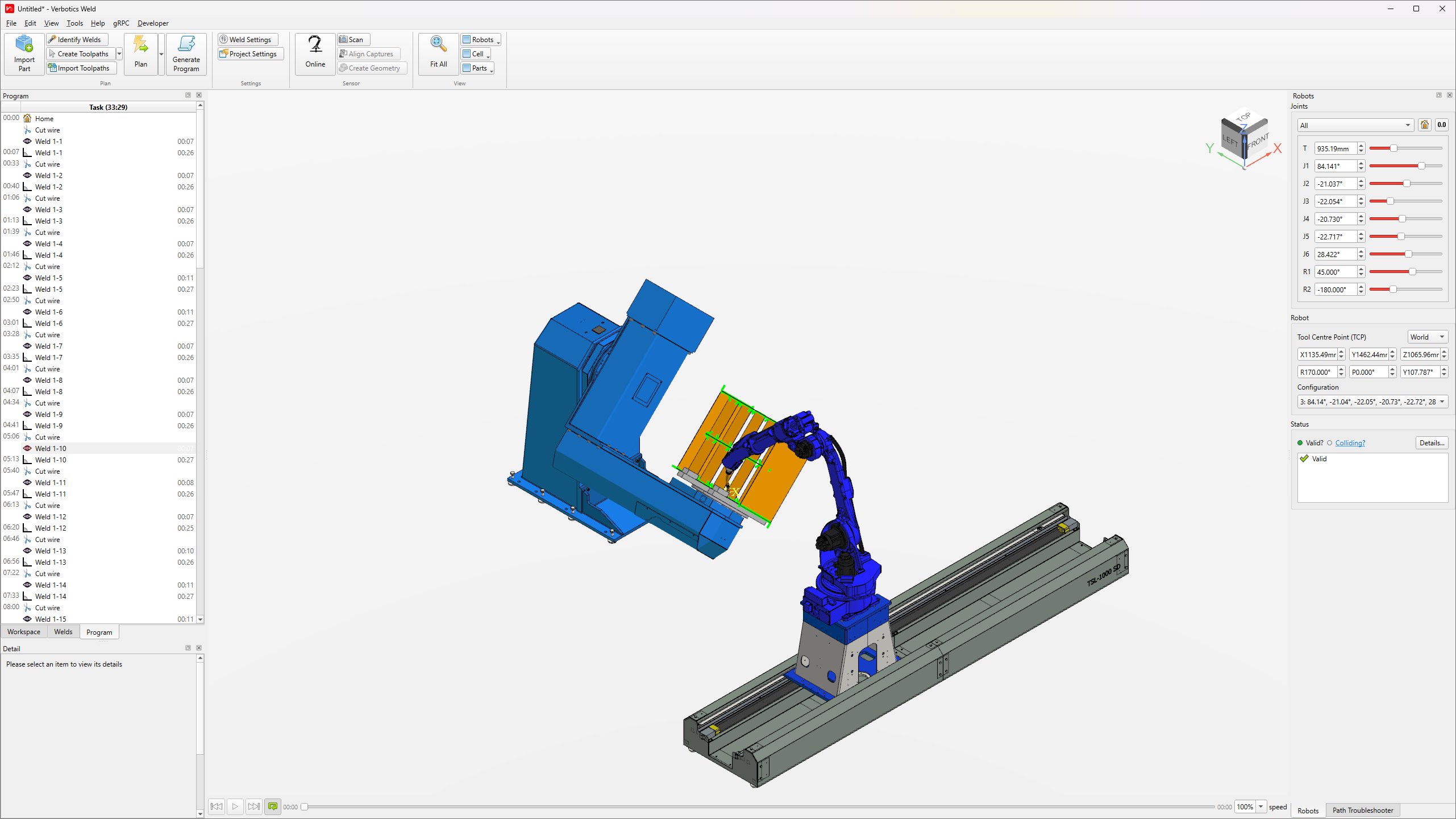
Simulating the Planned Welds Program
Generate Code
The final step is to generate code for your robot. In the trial version, code generation is not available. Please contact us if you would like to access sample code or discuss purchasing Verbotics Weld. For currently supported robot makes, please see the Supported Robots page.